
| SpaceClaim Online Help |
|
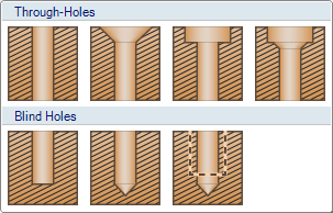
The Standard Hole tool creates industry standard drilled and tapped holes. Select one of the available standards (ISO , UNC, etc.) and then choose from available sizes and specify other hole characteristics (Blind, Tapped, Countersink, Counterbore, Drill point details).
The current hole profile is displayed in the Preview group. It dynamically updates as you define the hole. There is also a gallery of common hole profiles to choose from.
Hovering over the Preview shows the hole's definition, as it would appear in a Hole Table.
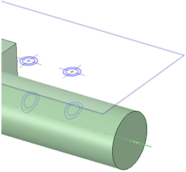
While choosing a placement location, a preview of the hole opening, including countersink and/or counterbore, is attached to the cursor. This allows you to view the footprint of the hole as you locate it.
Click  Standard Hole in theManufacturing group of the Insert tab.
The Hole Toolbar opens. Groups in the toolbar contain the options and inputs for hole definition.
Set options and enter values to define the hole.
May be determined by Series and Size. If so, you can still enter a different value. The value you enter will be displayed in bold font to indicate it is non-standard
Default thread depth is twice the basic hole diameter
that only the most common Standard Hole sizes have cosmetic display and can be toggled on/off
Countersink Counterbore Both


Determine countersink depth
Some Series specify both dimensions, some specify one, and others specify none
If they are specified, you can still enter a different value but it will be displayed in bold font to indicate it is non-standard
Diameter and Depth
Preview shows the hole profile based on current selections and values. Shown below is a Blind, Tapped, Countersunk, and Counterbored hole with Drill point details.

As you work with different inputs, Preview gives visual feedback. Below are examples of what you would see when entering values for Diameter, Hole Depth, Countersink Angle, and Drill point Angle.


Preview also has a gallery of profiles to choose from. Click on the Preview image to open the gallery.
The gallery is a graphical way to define the hole. Selecting a hole from the gallery automatically fills in the details in the ribbon.
Choose a tool guide for hole placement.
Complete the hole(s) by clicking ![]() Complete. All previewed holes will be completed. You can also double-click when you place a hole to complete it.
Complete. All previewed holes will be completed. You can also double-click when you place a hole to complete it.
Continue to make more holes or leave the Hole toolbar.
Click in the Close group to close the toolbar.
Hole Size and Fit options are determined by which Series you choose.
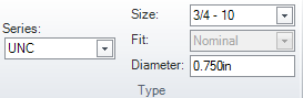
The examples below show the difference between ISO and UNC. Notice the change in Size nomenclature and Fit options. ISO has Fit options of Nominal, Close, Medium, and Free.
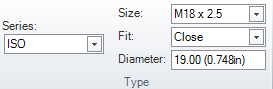
Fit is disabled in UNC.

|
As of SpaceClaim 2014 SP1, the NPS series is replaced by NPSM. Standard Holes created using NPS in existing models will not be recognized. |
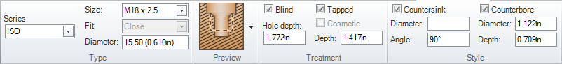
The image below shows the ISO M18 x 2.5 ribbon.
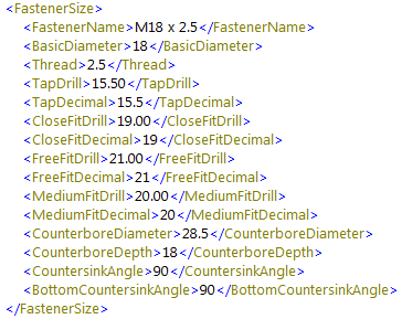
The XML for this ISO hole size is in the ISO.xml file. The relevant XML is shown below.
Notice the correspondance between the XML tags and the ribbon inputs.
All dimensions are in millimeters and angles are in degrees.
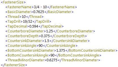
The image below shows the result of switching to the UNC Series and the 3/4 - 10 Size.
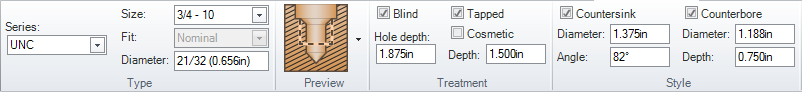
The XML for this UNC hole size is in the UNC.xml file. The relevant XML is shown below.
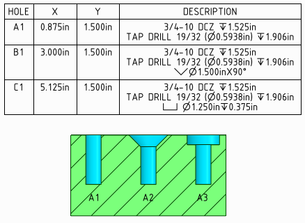
The image below shows the values in the XML file show up in a Hole Table created in a drawing.
You can edit any of the series XML files to customize the series.
that edited files will be overwritten the next time you upgrade to a newer version of SpaceClaimIt is recommended that you customize the series by adding files to the directory.
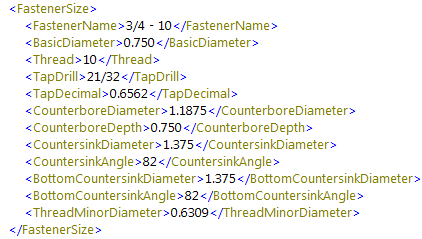
The image below shows a "DCZ" series added.
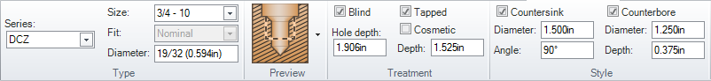
The DCZ series is based on UNC by copying UNC.xml to DCZ.xml and editing the sizes.
the new TapDrill value reflected in the Diameter input and the new Countersink and Counterbore values.
Drill chart is a Series based only on Diameter values. It refers to a set of XML files that contain hole definition tables. Edit the files to customize the Standard Hole tool.
In the <SpaceClaim loadpoint>\Libraries\Holes\Drills directory, you will find the following files:
File names refer to how the hole name is specified. Below is an example from Letter.xml.
<Name>A</Name>
<Diameter>0.234</Diameter>
<ImperialDisplay>0.234</ImperialDisplay>
<MetricDisplay>5.94</MetricDisplay>
Modify the files according to this format to define custom holes.
SpaceClaim recognizes Standard Holes. Hovering over a hole face will pre-highlight the hole object.
Select individual hole faces using query select.
Deleting any Standard Hole face, or the face it was created on, breaks the Standard Hole association. Individual faces are still selectable, but are not recognized as a Standard Hole.
You can also CTRL select, or box-select, several holes that share any of the same parameters.
Open the Standard Hole Edit tab. You can also double-click a Standard Hole to open the Edit tab.
The Edit tab is not available for multiple holes that share no parameters.
Edit the Hole definition.
You can continue to select and Edit more holes.
To close the Edit tab:
Select a non-hole object
Click white space in the Design window
Enter selection for another tool
With a Standard Hole selected, you can use the Reverse Hole option in the context menu to flip the hole to the opposite side of the part.
© Copyright 2014 SpaceClaim Corporation. All rights reserved.

 Free Placement