| SpaceClaim Online Help |
|
Semantic GD&T symbols understand their dimensional and situational context within the model. So, when their attachment references change in space or in type, the semantic symbols update accordingly or become invalid.
GD&T is part of the Product and Manufacturing Information (PMI ) exchanged between CAD systems. The PMI Working Group recognizes two levels of information that can be exchanged in the context of explicit 3D geometric shape representation and associated PMI.
that is not visible in the 3D model. It is used "behind the scenes" by the CAD system and downstream applications.In , Representation information is pointed to by the definitions shown in the Structure Tree. The geometry that the definitions apply to are recognized as features which are displayed in the tree. Definitions which apply to the features are shown as sub-nodes of the features in the tree. This includes dimensions for features of size. All GD&T items in the Structure Tree are contained in the 'GD&T' folder as shown in the image below.
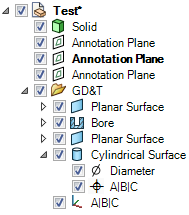
GD&T has its own Structure Tree folder.
Presentation information is the actual symbol shown in the graphics area and attached to geometry.
Representation stays with the object because it is part of its Structure. Presentation information is built from the representation.
So, when a solid with associated Semantic GD&T is moved to a new component:
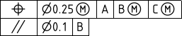
To build a semantic GD&T symbol, you construct a Feature Control Frame, which consists of a rectangle divided into compartments containing:
Feature references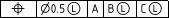
Prior to creating the symbol, you need to have the appropriate Datum Features  in the model.
The geometry to which a GD&T symbol is applied is usually called a "Feature". Features may be specified by:
After choosing a Characteristic Symbol and the geometry (usually called Features) to which the tolerance will apply, you will be asked to select the relevant Datum Feature references
An exception is Form tolerances, which do not use Datum Feature references.
When you first create a GD&T symbol, the default Characteristic Symbol is Position. Once you choose a different symbol, that becomes the default until you select another one.
Characteristic Symbols are shown in the table below.
Tolerance Type | Symbols | Applied To | |||
Form |
Straightness |
Flatness |
Circularity |
Cylindricity | Individual Features |
|
| Individual or Related Features | |||
Orientation |
Angularity |
Perpendicularity |
Parallelism | Related Features | |
Location |
Position |
Concentricity |
Symmetry | Related Features | |
Runout |
Runout |
Total Runout | Related Features | ||
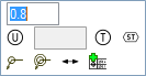
Once you have selected the Datum Feature references, you are put in placement mode where:
Symbol tool to create any Datum Features to be referenced by the symbol. (Datum Symbols are semantic as well)
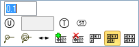
(see the table below)After the symbol has been placed, you can add any appropriate modifiers by
Reference compartments to be modifiedWhen you select a symbol element, the mini-toolbar will present all relevant modifiers.
Their meaning and applicability are described in the relevant sections of ASME Y14.5 (2009) and ASME Y14.41.
Available Modifiers are shown below.
Symbol | Modifier |
| At Maximum Material At Maximum Material |
| At Least Material At Least Material |
| Translation |
| Projected Tolerance Zone |
| Free State |
| |
| Unequally Disposed Profile |
| Statistical Tolerance |
| Between |
| All Around |
| All Over |
Some notes about Modifiers:
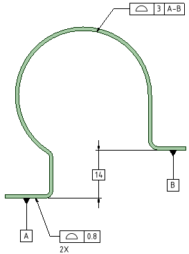
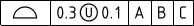
References (A, B, C, etc.) to indicate the datum can translate within the specified tolerance. Plane is applied to tolerances of Form only. is applied to Profile tolerances to indicate that the tolerance is not equally applied to the profile. For example, the symbol below the modifier is between 0.3 and 0.1. This means the total tolerance is 0.3 and 0.1 lies Outside the profile and Adds material. The remaining 0.2 lies Inside the profile and Removes material.
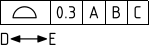
Between indicates that the tolerance applies across multiple features or to a limited segment of a feature between designated extremities.
The example below shows a profile tolerance between D and E. The system prompts you to select a direction and a first and last face to include (first and last can be the same face). It places labels based on the next available letters but you need to create notes pointing to the locations on the faces.
Select the Profile tolerance to modify
Choose Between from the mini-toolbar
Select an edge to set the direction of the limited region or group of features
Select the first face
Select the last face
Complete
of Surface symbols attached to dimensions (Attachment Technique = Size Callout)
You can add segments to GD&T symbols in much the same way as they are initially created.
Instead of selecting geometry, you select the Characteristic Symbol of an existing GD&T symbol.
Based on which Characteristic symbol you wish to add, the system will limit which existing symbols are available.
For example, adding Concentricity to the position tolerance of a hole is invalid.
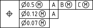
A Feature-Relating Tolerance Zone Framework (FRTZF) contains a single entry of a Characteristic Symbol followed by each tolerance and datum requirement, one above the other.
FRTZF applies to Position and Profile tolerances used with Patterns.
Each segment can have the same number of Datum Feature References or Less than the segment above it.
To create a FRTZF:
tolerance value
To set the FRTZF Datum Feature References:
Select the first secondary tolerance value
The mini-toolbar appears
The mini-toolbar options will adjust depending on which segment tolerance is selected.
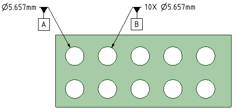
For patterns, you can create a Datum Feature Symbol that applies to a single member only, or the whole pattern.
In the Options panel, check the Use One Pattern Member Only option On to apply the symbol only to the selected pattern member. Check it Off to apply the symbol to the entire pattern.
The image below shows an example. For the entire pattern, the number of pattern members is included in the symbol.
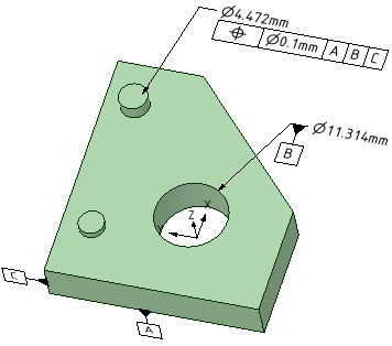
The Datum Reference Frame (DRF) consists of three mutually perpendicular planes inferred from three Datum Features.
Datum Features that comprise the DRF can be a combination of planes and cylinders.
The DRF is inferred from the Datum Feature References. This does not mean the references have to be three orthogonal planar features.
The XYZ coordinate system in the image above is the Datum Reference Frame formed by the three Datum Features A, B, and C.
When you select a DRF in the Structure Tree, it highlights in the Graphics Window. Likewise, selecting a DRF in the Graphics Window highlights it in the Structure Tree.
The DRF may not be valid if changes have been made to invalidate any of the symbols. Invalid Datum Features are marked with a Red 'X' in the Structure Tree.
You can Delete a DRF by selecting it in the Structure Tree like other SpaceClaim objects.
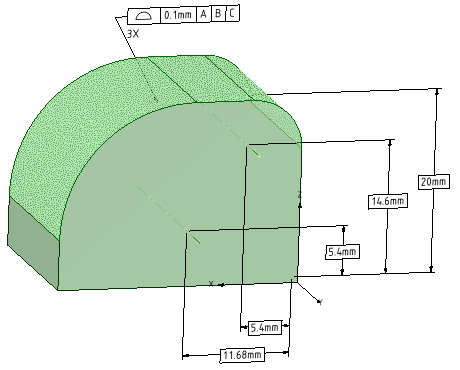
Basic Dimensions locate the controlled features back to the Datum Reference Frame. They are generated automatically once the DRF is established. All you need to do is place them.
are available to switch between the different directions (X, Y, Z) and to change annotation plane.The image below shows Basic Dimensions for a Surface Profile tolerance.
You can recreate Datum Feature symbols and Feature Control Frames in the graphics window and drawing views from symbols listed in the Structure Tree.
If you select a Datum Feature in the tree, follow the same procedure but use RMB > Create Datum Feature symbol
© Copyright 2014 SpaceClaim Corporation. All rights reserved.