
| SpaceClaim Online Help |
|
The Wrap tool lets you wrap geometry around a target model. The example below shows both a solid and a surface wrapped onto a cylinder.
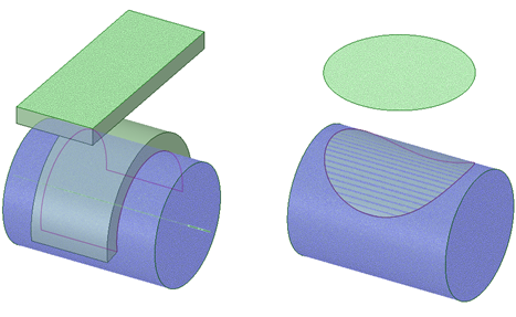
A solid block and a circular surface are wrapped around a cylindrical target body using the Wrap tool.
Sketched Curves and Notes can also be wrapped around a target body.
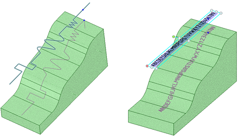
Sketched Curves and a Note are wrapped around a target body using the Wrap tool.
Layers of solid geometry can be wrapped. Consider a circuit board that is not flat, for example. Components layered onto the board need to follow the contours of the board. An example of the final circuit board is shown below with transparency in the board to show a component underneath.

A contoured circuit board with layers of components wrapped onto it.
The starting model for the circuit board is shown below. Notice that the components are at two different heights and they extend beyond the board. The spacing of the solids is based on their proximity to the first selected solid to be wrapped.
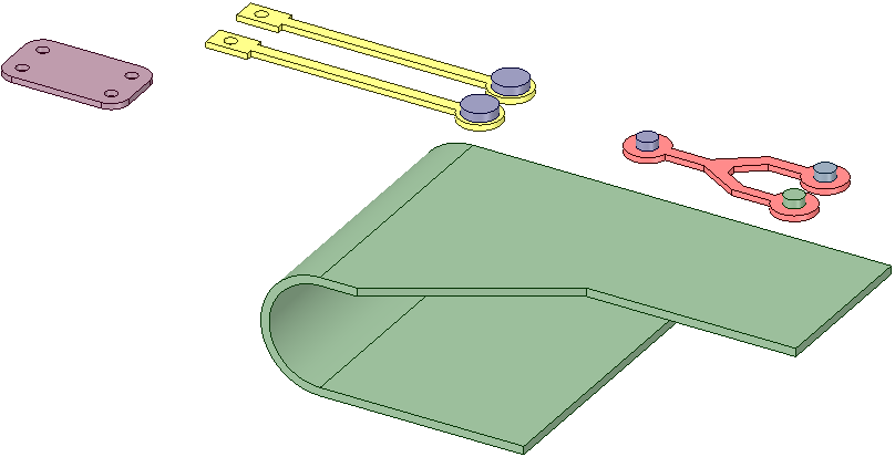
Components are about to be wrapped onto the contoured board.
The board is selected as the target and the first set of components is selected for wrapping. it includes a base layer of components and a second layer that rest on top of the first. Notice the starting point indicated by the yellow handles on the right. By default, the handle locations are set to the shortest distance between the Source and the Target. They can be moved to different locations if desired. In the image below, the default location is used for the first set of components. The wrapped locations are previewed in purple.
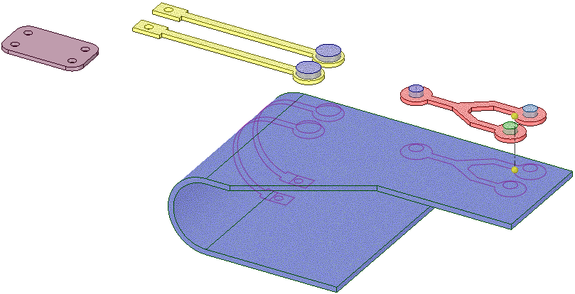
The wrapped component locations are highlighted in purple.
The image below shows the completed wrap for the first set of components.
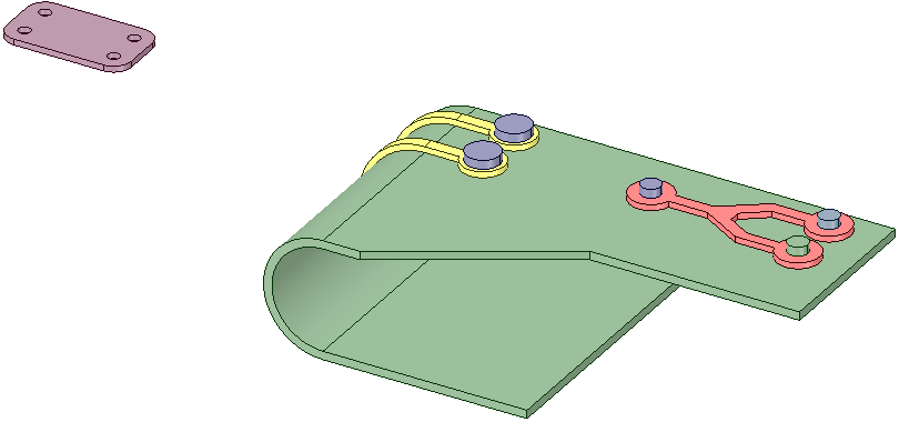
The first set of wrapped components is completed.
The last component gets wrapped underneath the board. Notice how the start point is initially at the shortest distance. This would distort its spacing relative to the first set of components.
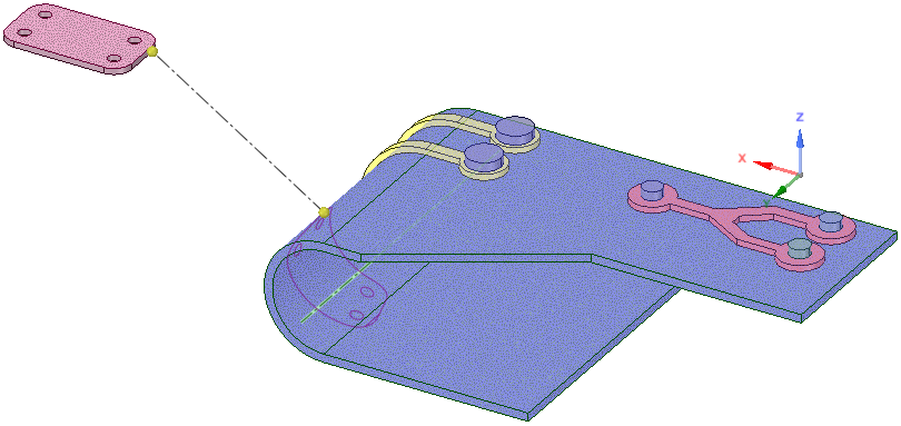
The default spacing of the last component.
In order for the component to map too the correct location, an origin is selected as the start point. This will maintain the original spacing of the component relative to the other components.

Using an origin as the start point ensures the proper spacing.
There are two options for the Wrap tool.
and surface boundaries, and curves, are imprinted on the target.Open the Insert tab.
tool guide is active by default. body. Point or Origin to use as a start point for the wrap.
You can drag the source and target start points to reposition the wrap
© Copyright 2015 SpaceClaim Corporation. All rights reserved.