
| SpaceClaim Online Help |
|
Curve Tables contain information about selected curves. They apply to:
curvesThe image below is an example of Turn Profile curves.
Curve tables are similar to Hole Tables.
The following information is included in the table.
or Arc tab. group.. for locating the curves.Box-selection is available.
If all the curves are in the same plane, that plane is used for placement by default. If the curves are in multiple planes, drag the cursor over the model to highlight planes and select one.
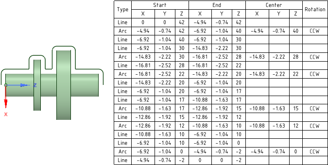
Manufacturing-focused tables are created for Turn Profile curves. They contain information that is useful for programming the turning machine.

|
When working with Turn Profile curves, make sure you Alt-select an origin when you create the Turn Profile. This ensures that the curves are in-plane and will generate rotations properly for Manufacturing-Focused Tables. |
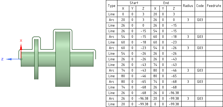
The following information is included in the table.
to enable the manufacturing options. if you want to list arc radius in the table.Box-selection is available.
If all the curves are in the same plane, that plane is used for placement by default. If the curves are in multiple planes, drag the cursor over the model to highlight planes and select one.
The image below shows a Curve Table using I, J, K values.

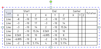
A Snapshot table breaks a 3D curve or curves into straight line segments and reports the endpoints of the segments. An example is shown below.

Box-selection is available.
If all the curves are in the same plane, that plane is used for placement by default. If the curves are in multiple planes, drag the cursor over the model to highlight planes and select one.
The default ordering scheme comes from manufacturing turning operations, where the workpiece is set up as shown in the image above. The Z-axis is aligned with the turning axis and the tool bit moves from the most positive Z location to the most negative Z location. The start and end points in curve chains begin at the largest positive Z value and move toward lesser Z values.
The default ordering scheme is used when you box-select the curves.
Individually selected curves (using the Ctrl key), or curves selected by range (select the start curve then Shift-select the end curve), are ordered in their selection order.
Randomly selected curves, that were selected without curve order in mind, will be ordered using the default scheme.
When you change the size of a hole, the values in the table update, and the table re-orders and re-classifies the holes and rows of the table.
To remove a table, select the table, right-mouse click, and select Cut, or press the Delete key.
© Copyright 2015 SpaceClaim Corporation. All rights reserved.