| SpaceClaim Online Help |
|
Use the Convert tool to convert solid bodies into mesh bodies.
Use the following Convert options to control the size and shape of the mesh facets in areas with curvature.

These are the same options (geometrically-speaking) as the ones that control STL export.
Regardless of the context in which these options are used, they control the facet creation required by mesh modeling tools, whether it is for the explicit, user-directed Convert, or the behind-the-scenes conversion required by other mesh modeling tools.
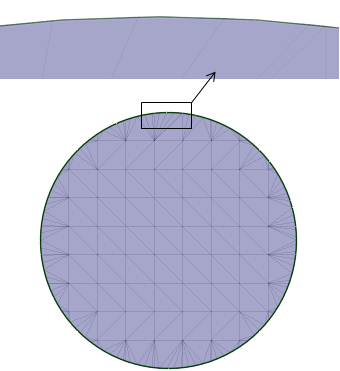
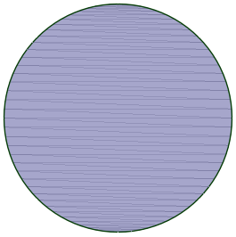
Max distance controls how far facet edges are away from model edges. The images below show the effect of Max distance on the mesh of a cylinder. These examples keep the Aspect ratio fixed at 3 and the Max edge length set to 4 mm.
|
|
|
|
Max Distance = 0.75mm Max angle = 20-degrees |
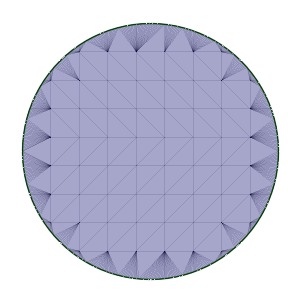
Max Distance = 0.01mm Max angle = 20-degrees |
Notice how the settings change the facets along the edge of the circle. The intrerior is a flat plane, so 45-degree triangles are the most efficient facets.
The example on the left shows the default Max distance of 0.75mm. This refers to the gap seen in the zoomed-in (top) image. Decreasing the Max distance to 0.01mm results in more facets along the edge, which brings the facet edges closer to the cylinder edge, as seen in the example on the right.
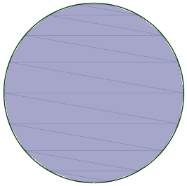
Similarly, decreasing the Max angle will result in more facets along curved edges. This example shows the result of decreasing the Max angle from 20 degrees to 1 degree.
|
|
|
Max Distance = 0.75mm Max angle = 1-degree |
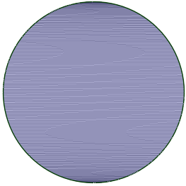
Without a fixed Aspect ratio and without a Max edge length, you can get more distorted triangles as shown in the following images.
|
|
|
|
|
No set Aspect Ratio or Maximum Edge Max Distance = 0.75 mm Max angle = 20-degrees |
No set Aspect Ratio or Maximum Edge Length Max Distance = 0.75 mm Max angle = 1-degree |
No set Aspect Ratio or Maximum Edge Length Max Distance = 0.01 mm Max angle = 20-degrees |
Converting a solid body to a mesh consumes the original solid.
Use the Keep original bodies option if you want to retain the original solid bodies.
The Convert tool also has a Progress Bar and a Stop button for meshes that take longer to generate.
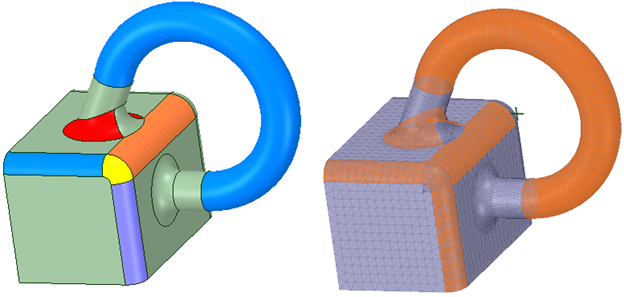
When converting a B-Rep model to a faceted model, you can double-click a face to select the underlying topology. In this example, the first image shows the original model. The second image shows the faceted model with faces selected (shown in orange). The selected faces correspond to the colored faces in the original model.
© Copyright 2016 SpaceClaim Corporation. All rights reserved.