
| SpaceClaim Online Help |
|
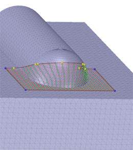
The Skin Surface tool helps you reverse-engineer a surface model from faceted data. For example, the starting point of your design may be a clay model which is scanned and output to one of the supported faceted data types. After you import the faceted data as a Facet Mesh, use the Skin Surface tool to sketch and create surface patches on the facets, and stitch them together into a surface body.
 Skin Surface tool in the Reverse Engineering group of the Insert tab
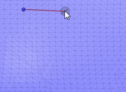
The following options are available in the Skin Surface tool.
|
Samples |
The value entered determines the number of Control Points on the Control Curves for the surface. By default, the number of sample points is fixed and cannot be changed. If you check the Full Preview option, you can enter a new number of sample points. In Full Preview mode you can enter a new number of points directly, or use the dropdown slider. |
|
Smooth |
The quality and density of the mesh can affect the quality of the surface you create. The Smooth option uses an algorithm (similar to blurring algorithms in image processing) to smooth out the 'noise' in the surface. The noise comes from the underlying facets and leads to a 'bumpy' surface. |
|
Full Preview |
When you check Full Preview ON, you can control the number of sample points used in the surface. In Full Preview mode, when you change the number of sample points, the preview dynamically updates. The speed of the dynamic updates is affected by the number of sample points. Fewer points leads to faster updates. |
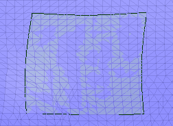
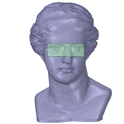
Notes on the Smooth tool guide:
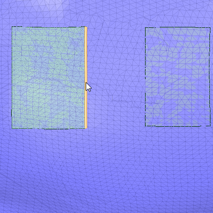
The following example model is used to illustrate the effects of the Smooth tool guide. Two surface were created in the same location, as indicated by the highlighted rectangular surface.
|
|
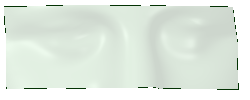
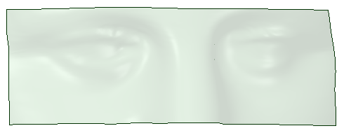
| This surface was created with Smooth set at 100%. Notice that it has less detail and smoother features than the surface on the right. | This surface was created with the Smooth option checked OFF. Notice that it has more detail and sharper features than the surface on the left. |

|
Use the Smooth tool the Facets tab to smooth the facets if you cannot get a smooth enough surface using the Smooth option in the Skin Surface tool. |
The following tool guides help step you through the process. Use the Tab key to cycle through them. As soon as the tool guide switches, the cursor may change to reflect the active guide.
|
|
The Select Boundary tool guide is active by default. When this tool guide is active, you sketch surface patch boundaries on the facets. |
|
|
The Select Geometry tool guide lets you choose planes or existing patch edges to create boundary loops for surface patches. |
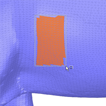
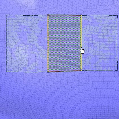
If you want to work with rectangular patches, use box-select instead of sketching them freehand. With the Select Boundary tool guide active, simply box-select the area where you want the sketch.
|
|
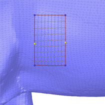
| Box-select facets | Sketch is made from the box-selection |
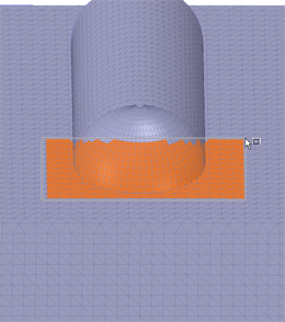
Notice that control points are automatically added in areas with curvature. This can be seen more dramatically in the images below.
|
|
|
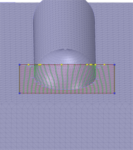
| Box-select across a curved area | Control points are auto-created | Change view to see the curvature |
While in Preview, you can modify the shape of a sketch by dragging the corners and control points. Control Points are the internal points on edges that allow you to adjust the edge's curvature. You can also add control points to give you more curvature control on edges.
The images below show a sketch being adjusted to better fit to the contours of the model and show a control point being added for further adjustments.
|
|
|
| Dragging a corner | Dragging a control point | Adding a control point |
Surfaces that wrap around cylindrical, and roughly cylindrical, volumes are called Periodic surfaces. They look like a rectangular patch wrapped around the volume.
Sketching these by hand can be tedious because you need to rotate the model to expose more facets on which to sketch.
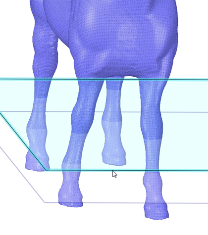
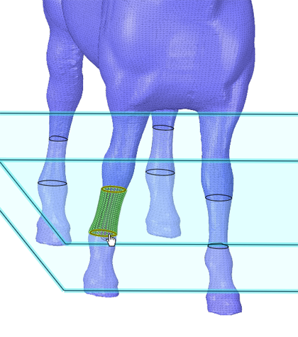
The Select Geometry tool guide streamlines the process by letting you select planes that create sections through the volume. The sections are then used to automatically generate sketch curves. Selecting two planes some distance apart automatically, creates the periodic surface.
In the following example, there are multiple periodic surfaces possible. Skin Surface previews one by default. If it is not the one you want, you simply select the edges of the one you do want.
| Two planes intersect the four legs. |
|
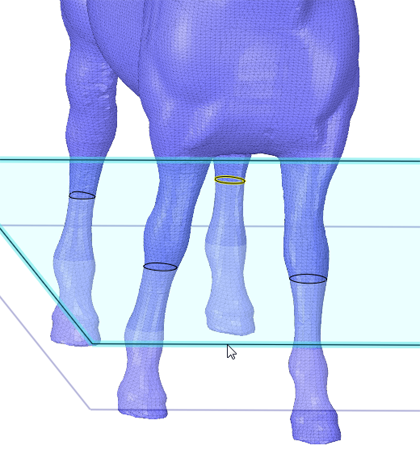
| Selecting the first plane displays sections on all four legs. |
|
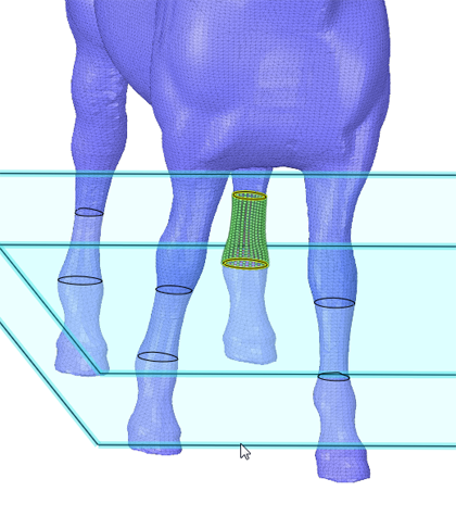
| Selecting the second plane displays the other four sections and the default surface. |
|
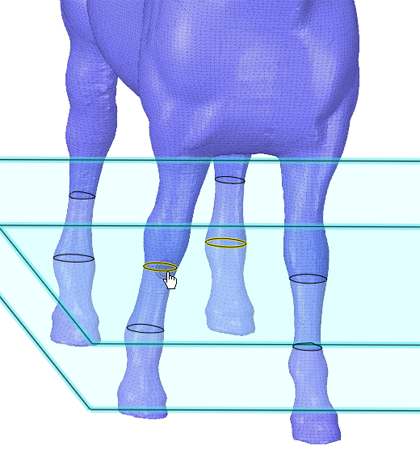
| To create a different surface, select the first section of the surface you want. |
|
|
Select the second section to display the surface preview.
Click Complete to create the surface. |
|
Conical Patches:
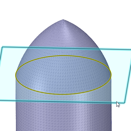
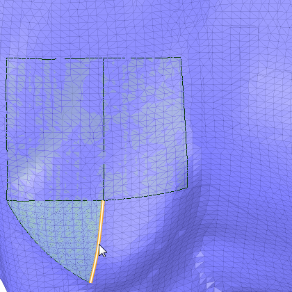
Periodic surfaces can also be conical. The following example shows how to create a conical surface patch.
| You can either sketch a periodic edge manually, or use the Select Geometry tool guide and a plane to create a periodic edge on the section. |
|
|
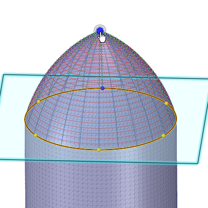
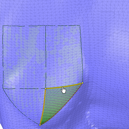
Click on the apex of the cone to preview the surface.
Click Complete to create the surface. |
|
Existing skin surfaces can be 'stitched' into a single surface patch. Examples are shown below.
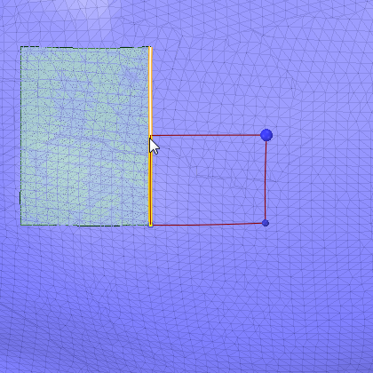
Use the Select Geometry tool guide to select rectangular edges:
| You can bridge the gap between rectangular patches using the Select Geometry tool guide. pre-highlight and select one edge. |
|
|
Pre-highlight and select the second edge to preview the surface.
Click Complete to create the surface. |
|
Use the Select Geometry tool guide to select triangular edges:
| The same procedure works for triangular patches. Pre-highlight and select the first edge. |
|
|
Pre-highlight and select the second edge to preview the surface.
Click Complete to create the surface. |
|
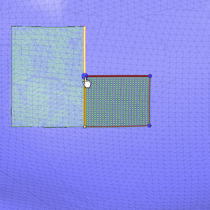
Snap to existing patch edges and points:
|
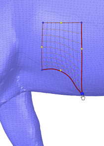
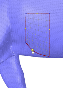
Withe the Select Boundary tool guide active, you can snap to existing surfaces. Here, the sketch started by snapping to the bottom corner. The color and size of the start point indicate that it is snapped to the lower right corner of the existing surface.
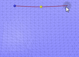
The sketch then proceeds in a counterclockwise direction.
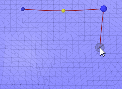
The end of the third edge snaps to the existing edge, which is highlighted to indicate it will be used.
The fourth edge is auto-completed by the tool and is shown on top of the snapped edge.
|
|
|
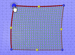
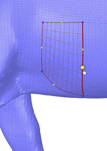
A single click completes the third and fourth edges and the surface previews.
Click Complete to create the surface. |
|
|
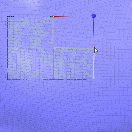
The next sketch begins at the upper right corner of the first surface. Like the previous sketch, the color and size of the start point indicate that it is snapped.
The sketch proceeds in a clockwise direction.
When the second edge reaches the upper right corner of the previous surface, the corner and edge of that surface highlight to indicate they will be used.
Two edges can auto-complete to complete the loop. They are highlighted on top of the existing edges that will be used. |
|
|
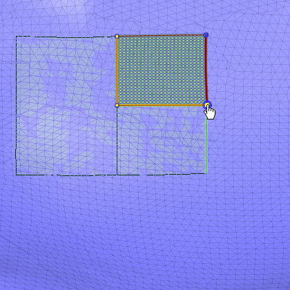
A single click completes the second, third, and fourth edges and the surface previews.
Click Complete to create the surface. |
|
© Copyright 2016 SpaceClaim Corporation. All rights reserved.

