
| SpaceClaim Online Help |
|
SpaceClaim can share topology (face, edge, and vertex connections) between touching or intersecting bodies and surfaces in designs that are transferred to ANSYS.
Shared topology is the only way to achieve a conformal mesh where bodies meet, and is the only way to be certain that the intersection of bodies is meshed perfectly.
Shared topology also applies to volume and surface bodies that are completely inside of other volume or surface bodies. This situation is common in analyses involving fluid flow.
The Shared Topology settings are:
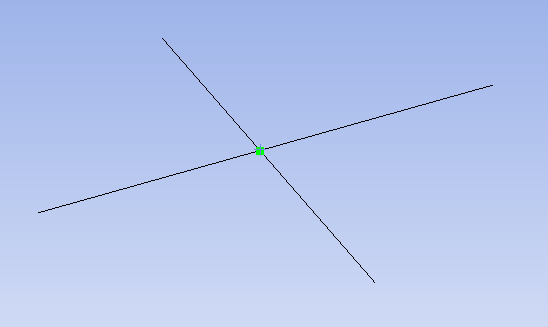
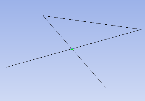
 edges that lie on the solid are valid. Surfaces that intersect the solid are not valid and must be trimmed before executing Shared Topology.
For ANSYS 15.0 and later, Shared Topology set to Merged applies to the following cases:
A is completely inside of Solid B which is completely inside of Solid C. Solid A will share topology with Solid B and Solid B will share topology with Solid C.For ANSYS 17.0 and later, Shared Topology set to Group will group all bodies in a component into a multi-body part in ANSYS/Workbench. It does NOT merge or share faces and edges of the bodies with each other.
Beams that are in the same component and have the same properties (i.e. Cross Section, Anchor, Material), are transferred to Workbench as follows, when Shared Topology is set to Merge, Share, or Group:
See the Shared topology tutorial for hands-on experience with shared topology. See ANSYS online help for detailed information about how ANSYS handles multi-body parts and shared topology.
Put the bodies anywhere under a component that has its Shared Topology property set to Shared (or Merged in ANSYS 15.0 and 16.0), including a sub-assembly (regardless of the sub-assembly's Shared Topology setting).
This property can be found in the properties panel when you select one or more components in the Structure tree.
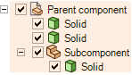
The Shared Topology property on Parent component is set to true, so the solids inside the shaded area are shared.
Place solids in a component whose Shared Topology property is set to None, and whose parent components also have this property set to None.
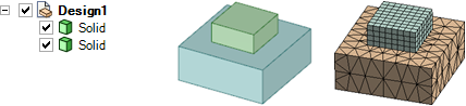
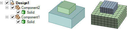
ANSYS meshes two blocks with shared topology. The blue block will gain a new imprinted face which will be shared between the green and blue blocks. Notice how the nodes of the mesh line up along the bottom of the smaller block.
ANSYS creates separate meshes for two parts because they are in different components and the root part has Shared Topology set to None.
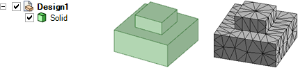
The mesh for shared topology is not the same as merged geometry. Here the boxes are merged, and you can see that the mesh is different than it is for two bodies with shared topology.
© Copyright 2016 SpaceClaim Corporation. All rights reserved.