|
SpaceClaim Online Help
|

|
You are here: Working with SpaceClaim documents > Importing and exporting
Importing and exporting
Use the Open command to open files created in any supported format. Use the Save As command to export parts, assemblies, drawing sheets, and 3D markups to formats read by other applications. Your license type determines which of these actions are supported.
If you work frequently with non- files, we recommend that you set your file options to optimize the importing and exporting process for your needs.
IDs for edges, faces, and bodies are now stored within the .scdoc file. Object IDs are preserved when other files are opened or inserted into, and the IDs can also be exported. For example, if you export a design to an analysis company, and they tag geometry with load positions, boundary conditions, and so on, then when you re-import that design, make changes, and re-export to the analysis company, they will not need to recreate their tags on the new design.
If you import a file and it fails, the reason for the failure is reported in the Status Log on the lower right edge of the window.
To import a design
-
Select Open from the File menu or click  in the Quick Access toolbar, or click the Insert tool in the Insert ribbon group on the tab.
Depending on the selected file type, additional elements appear in the Open window. For descriptions of these options or to set their default values, click Options.
-
Select Check geometry to run the geometry check after the file is opened or imported. See Checking geometry.
-
Navigate to and select the file you want to open or insert.
If you are opening a file, it is displayed in a new . If you are inserting a file, it appears as an external component within the active design.
If there is an invalid character in the path of a file you are trying to open or insert, that character is replaced with a valid character to avoid errors.
If you open an Inventor, Pro/ENGINEER, or Unigraphics file that has missing components, you will be prompted to locate the missing files.
Click Stop in the status bar to cancel an import while it is in progress.
The name of the imported file is displayed in the Status Log when it is successful.
Expand the sections below for information about a specific file format.
To export a design or 3D markup
-
Select Save as from the File menu.
You can also press F12 or Ctrl+Shift+S.
Your design must be saved as a document before you can export it in another format.
-
Select a file type from the Save as type drop-down.
-
Depending on the selected file type, additional options appear in the Save As window:
-
Save as copy if you want to save copies of external components referenced by the design with new names or replace external components with other external components. You must click Resources to do this.
-
References to display all the external components referenced by the file. Select one or more external components and click Browse to rename or replace the components.
-
Override Units is available when you export some file types. Select the units from the list.
-
Options to also set your default export options for the selected file type.
-
Improve data on export to clean up imprinted edges and split curves when you export data.
-
Units Depends on file type
-
Choose a standard view
-
Version Depends on file type
-
Export part manufacturing information (JT)
-
Use Perspective Camera for KeyShot
-
Store 3D data as: For PDF, choose either Geometry (PRC B-Rep) or Facets only (Universal 3D)
-
Convert components to Rhino layers
-
Protocol: For files can be 203 or 214.
-
Image size (pixels): For Bitmap, GIF, JPEG, PNG, TIFF files opens Image Size dialog
Hidden lines are exported with the default line weight. Components maintain their mirror relationships when they are exported.
For , , STL, and STEP files, you can select which version or protocol to save as. You can also set your default export options by clicking Options.
You can save documents that only contain sketch curves to binary (.sab), ACIS text (.sat), Parasolid, CATIA, IGES, STEP, and VDA formats. You can import and export free points for Rhino, PDF, ACIS, IGES, JT Open, Parasolid, STEP and VDA formats.
Imported designs with identical file names are given unique file names when you save your design. For example, if you imported name.prt and name.asm, these files are saved as name.scdoc and name2.scdoc.
Expand the sections below for information about a specific file format.
-
Browse to a folder and type a file name in the dialog.
-
Click Save.
Import: Supported File Types
Up to R27 (2017 1.0)
3D - parts, assemblies
.sat, .sab, .asat, .asab
-
When you save an SAT file to an X_T file, bad edges are cleaned up in the design.
-
When you import ACIS files, the instance name "part n (body m)" is now imported, but only if the body name is different from the part name. The component and body names are separated by a character which you can define in the options for ACIS files. For example, the default character is a period, so the imported name would be component.body. This way, if there were one body named wheel in one component, the name of the imported component in SC would be wheel. An instance is a copy of a body (a copied or pattered solid).
-
ACIS bodies can be imported using the RealDWG option, Sketch curves and text can be imported into Designs, 2D.
- Part and level can be imported from ACIS.
Facets, 3D - parts, assemblies, Geometry (PRC B-Rep)
.pdf
- 32-bit and 64-bit platforms are supported.
- Color information is imported for 3D PDFs.
- Supports B-REP import and export
- Defaults to B-Rep when exporting
- Importing PMI as graphical objects - not semantic - is supported.
- Notes
- Geometric Tolerances
- Finishes
- Symbols
- Datum Targets
- No Adobe Acrobat required for B-REP import and export, 32bit and 64bit platforms supported, Adobe Acrobat X Pro is not supported
- 3D PDF via a PRC neutral file along with Semantic PMI (if PMI data is present)
- Curves are imported from faceted data.
V1.0 (Facets)
3D - parts, assemblies
.amf
-
Import also supports compressed AMF.
-
You can stop AMF import using the Stop button when image processing takes too long.
-
names and colors are supported.
3D - parts, assemblies
.def
R12 to 14, 2000, 2004, 2007, 2010, 2013, 2016
modelspace and layout space entities including solids (ACIS V7 format)
Includes Polyface Meshes
.dwg, .dxf
-
drawings can be inserted as layouts.
-
If you import an AutoCAD file and you don't see the geometry you expect, try changing the import options. See File import and export options.
-
When you save a design with a shaded graphics style as a DWG file, it is converted to the hidden line style.
-
When you save a sheet metal design as a DXF file, notes and bend lines are saved on the same layer, and the overall unfold dimensions are removed.
-
weights can be exported to AutoCAD (DXF or DWG). Hatch lines on drawing sheets are exported as stand-alone lines.
-
You can import polyface meshes from AutoCAD files as 3D solids. See File import and export options for a list of polyface mesh import options.
-
imports "Proxy entities" in AutoCAD DXF and DWG files when you select the TeighaDWG option.
-
If an AutoCAD file won't open, try changing the DWG option to RealDWG. Some AutoCAD files contain embedded ACIS models; however, these may not be standard ACIS models. The RealDWG libraries contain an API to save back these variant ACIS models in the last common format, ACIS v7. The TeighaDWG libraries do not.
-
ACIS bodies can be imported using the RealDWG option, Polyface meshes import as lightweight (read-only), Sketch.
- Export as 2D snapshot
- Spaces are imported into separate windows.
- Empty Layout Spaces are ignored on import.
- Layout Spaces are only supported for Teigha, NOT RealDWG.
SPB (BRD, MCM, SIP)
parts and assemblies
- Cadence translators require an installation of Cadence SPB to be locally available
versions V4 4.1.9 to 4.2.4
parts, assemblies
.model, .CATPart, .CATProduct, .cgr, .exp
-
CATIA faceted (.cgr) files can be opened, but appear as lightweight components that cannot be loaded. You can save imported .cgr files as documents that can be opened later; however, this document’s content remains lightweight. It is visible in the Design window but you can't change the model.
- Part-level PMI
-
CATIA files with product manufacturing information (PMI) can be opened or inserted. Visibility is turned off. If a layer doesn't exist, it is created automatically.
-
Includes Product Manufacturing Information (PMI) placed on the Imported Planes.
- Import and export of free points is supported
- CGR imports Facets as mesh objects. SpaceClaim recommends editing meshes on a 64bit OS.
- Named selections of faces are created when importing geometrical sets.
- Publication Sets are imported as named selections.
versions V5 R8 to R25, V5-6R2016
parts, assemblies
.model, .CATPart, .CATProduct, .cgr, .exp
-
CATIA faceted (.cgr) files can be opened, but appear as lightweight components that cannot be loaded. You can save imported .cgr files as documents that can be opened later; however, this document’s content remains lightweight. It is visible in the Design window but you can't change the model.
- Part-level PMI
-
CATIA files with product manufacturing information (PMI) can be opened or inserted. Visibility is turned off. If a layer doesn't exist, it is created automatically.
-
When exporting CATIA V5 files, you can deselect the Simplify Surface Data option. When importing or exporting CATIA files, the XYZ locations of point objects scale correctly.
-
Includes Product Manufacturing Information (PMI) placed on the Imported Annotation Planes.
- Import and export of free points is supported
- CGR imports Facets as mesh objects. SpaceClaim recommends editing meshes on a 64bit OS.
- Named selections of faces are created when importing geometrical sets.
- Publication Sets are imported as named selections.
R2010x - R2016x
parts, assemblies
.3DXML
-
CATIA faceted (.cgr) files can be opened, but appear as lightweight components that cannot be loaded. You can save imported .cgr files as documents that can be opened later; however, this document’s content remains lightweight. It is visible in the Design window but you can't change the model.
-
CATIA files with product manufacturing information (PMI) can be opened or inserted. Visibility is turned off. If a layer doesn't exist, it is created automatically.
-
Includes Product Manufacturing Information (PMI) placed on the Imported Annotation Planes.
- Part-level PMI
- CATIA V6 precise part and product data must be exported as V5CATPart and CATProduct to be read into SpaceClaim.
- Import and export of free points is supported
- Named selections of faces are created when importing geometrical sets.
- Publication Sets are imported as named selections.
- For 3DXML, SCDM optional modules JT Open, 3D PDF, and CATIA V5/V6 are available.
(ANSYS SCDM only) V18.1 and V19, Creo 3.0
- Creo Elements/CoCreate software must be installed locally
- Only part level coordinate systems import if Import hidden components and geometry is checked ON in SpaceClaim General File options and Coordinate systems is also checked ON.
parts, assemblies
.agdb
(ANSYS SCDM only) Up to 16
- Assemblies are flattened
- Design Modeler software must be installed locally
IDF 3.0 and IDF 4.0
open IDF and PADS files
.idf, emn, .idb
-
Most content within IDF 4.0 files is supported.
-
Assembly of panels and boards, cutouts, filled areas, keep-ins, materials, panels and everything related, sublayouts, and thermal models are not supported.
-
Open IDF and PAD files
- IDF files can be synchronized with the imported model.
- Select any geometry in the model and use RMB > Update IDF to update the IDF file based on component operations performed in the model (e.g. moved components).
- The current SpaceClaim document must have been created by importing an IDF file.
- The source IDF file must be present on disk at its original location.
- A new IDF file is written that contains the updated information.
- The new file can be read back into the originating ECAD system to update the components.
ANF (SCDM Only)
.anf
ODB++
.tgz
EDB
.def in a .aedb folder
IPC2581
.xml, .cvg
GDSII
.gds, .sf, .stm
facets/mesh
.msh, .tgf
- Only surface/boundary mesh gets imported as a single faceted body
- The mesh units are assumed to be Meters
- Fluent-Meshing limits file and path names to ASCII characters only. Therefore, file names and file paths containing non-ASCII characters are not supported.
geometry
.tin
- Turn the Object names option ON in SpaceClaim Options > General file options to import ICEM CFD Part names. With an ANSYS license. Part names are always imported even if the Object names option is OFF.
- ICEM CFD Parts come in as separate bodies in SpaceClaim.
- With the Improve imported data option ON, the imported model may result in a formation of solid bodies and/or a Part structure different from what appears in ICEM CFD.
- Models containing faceted curves or surfaces are NOT supported.
- If a tetin file contains edges attached to faces and the edges and faces are in different ICEM CFD parts, the ICEM CFD part name for the edges will be lost as the edges are put in the part containing the faces.
- You can adjust values and re-run build topology in ICEM CFD to improve the success of the import.
- ICEM CFD limits file and path names to ASCII characters only. Therefore, file names and file paths containing non-ASCII characters are not supported.
parts, assemblies (versions up to 5.3)
.igs, .iges
- Curves and Colors are supported on import.
versions 6 – 10, 11 to 2016
parts, assemblies
.ipt, .iam
-
You can read the limitations here: http://doc.spatial.com/index.php/InterOp:Connect/Inventor/Inventor_Reader#Limitations.
-
Limited support for Inventor assembly
-
Assembly attributes such as colors and layers are not supported.
-
Inventor parts and Inventor sub-assemblies should be present in the main (root) of the Inventor Assembly directory.
-
Assembly level features are not supported. For example, an instance can be marked as suppressed (that is, not visible) in an Inventor assembly. Because the translator does not support reading suppressed information, suppressed instances are translated.
-
Inventor surfaces not supported
The translator currently does not handle "helical" surfaces in Inventor 6 files and "cylspl" surfaces in Inventor 7 files. If the Inventor file contains any of these surfaces, a partial translation takes place skipping the data for these surfaces and converting the remaining entities.
-
Limited entity support for Inventor 11, 2008, 2009, and 2010
The translator currently does not support some specific entities resulting from advanced feature Inventor operations such as Lofting.
-
No support for attributes
The translator does not support translating attributes such as colors and layers.
-
No support for hidden flag
The translator does not support filtering hidden bodies. Thus, all hidden bodies are translated as well.
-
Limited support for units
The translator supports only millimeter and inch for Inventor 6 – 11 and 2008. For versions 2009 and 2010, the translator supports only millimeter as unit. All unsupported units are assumed to be millimeter.
versions 6.4, 7.0, 8.0, 8.1, 8.2, 9.0 to 10.0
parts, assemblies
.jt
- JT Open 5.3 libraries are available for reading and writing JT files that were created with version 5.3.
- JT files with product manufacturing information (PMI) are supported for:
- datum labels
- text notes
- dimension measurements
- GD&T
- Weld symbols
- Flagnotes
- PMI option is ON by default (Part level PMI)
- PMI is placed on imported annotation planes
- Semantic and Polyline PMI are supported. Semantic imported dimensions will update with geometry changes. Polyline are simply curves in space that do not update.
- Semantic PMI is placed on Layer0 after import. Polyline is placed on a layer called Imported Polyline Annotations.
- For GD&T symbols, you can click any tolerance annotation or datum symbol to view its values in the .
- Click on an arrow or line to view or modify arrow or styles in the Properties panel.
- Unicode file names are supported.
- Import and export of free points is supported
- JT Open V6.4 and V7.0 imported and exported as faceted data
- SCDM optional module for JT Open is available
NX1 through NX10 and UG v11 through 18
parts, assemblies
.prt
V10.0 through V29
parts, assemblies
.x_t, .x_b, .xmt_txt, .xmt_bin
curves (insert only)
.txt
-
A spline curve is created by default or if the option Polyline=False is used. If the option Polyline=True is used, then the points are connected by straight line segments.
-
By default, 2D curves are created. When specifying 2D curves, the first column of the data points must be an integer and gives the height of the plane of one of the curves. The beginning of a new curve is specified by changing this height from one line to the next. If option 3D=True is used, the curves can be 3D
-
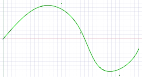
Use the Fit keyword to specify whether Curve Fitting or Interpolation is used.
Fit=True uses Curve Fitting. Curve Fitting creates a curve that "Fits" the data points using a specified tolerance. The curve may not pass exactly through all points and the distance from the curve to the point will be within the tolerance.
Use the Fittol keyword when Fit=Trueto specify the Curve Fitting tolerance in model units. For example Fittol=1.0e-2
The curve below uses Curve Fitting (i.e. Fit=true). A large tolerance (fittol=2.0) is used to exaggerate the fact that the curve does not pass through the points but only gets within the specified tolerance.
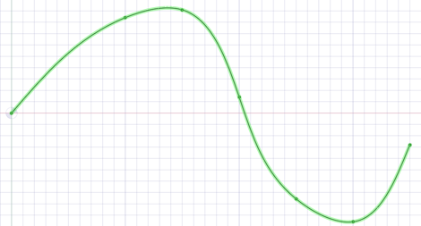
Fit=False uses Interpolation. Interpolation requires that the curve pass exactly through all of the points. An interpolation method is used to build a continuous curve through all of the points.
The curve below is interpolated (i.e. Fit=False). There are seven points in the file and the curve passes exactly through each one.
-
Multiple curves are separated by blank lines.
-
You can import point curve text files that contain single-point curves, which will be created as points.
-
-curve text files opened or inserted in display a closed curve when the file has a repeated value.
-
Curves can be imported to coordinate systems or other geometry like other imported objects.
-
Point-curve text files with columns separated by commas can be opened or inserted in . This feature allows you to import any comma-separated value file into .
-
If there is an error reading the input text file, a message will appear with the line number of the error in parentheses followed by the text appearing on that line.
-
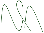
The following example shows the contents of a point curve text file on the left and the 3D curves it creates on the right:
-
that the point coordinates are (Z, X, Y).
-
For example (1, 2, 3) is (Z=1, X=2, Y=3).
|
3d=true
polyline=false
1 0 0
1 0 1
1 1 0
1 1 1
2 0 1
2 1 0
3 0 0
3 0 1
3 1 0
|
|
Keywords:
- polyline=false - spline curves are created.
- polyline=true - straight lines are created.
- 3d=true - 3D curves are created.
- 3d=false - curves are two-dimensional. This is also the case if the option is not set.
- fit=true - use Curve Fitting.
- Curve Fitting finds the "Best Fit" through the points.
- Does not require the curve to pass through all of the points
- fit=false - use Interpolation.
- Interpolation forces the curve to pass through all the points in the file.
- fittol=1.0e-2 - Curve Fitting tolerance in the units used in the file.
The blank line after the first set of coordinates indicates that the next set of coordinates is a new curve.
You can copy the file contents above and paste them into a text file, then use  Insert File to try it yourself.
Pro/E 16 through Wildfire 5.0 (Creo 1.0 to Creo 3.0)
parts, assemblies
.prt, .asm, .xpr, .xas
-
When you import Pro/ENGINEER assemblies and parts are missing, you will be prompted to search for the missing files
- For Pro/ENGINEER, semantic PMI import is supported.
-
For Wildfire 3 and above, PMI display information import is partially supported.
- Wildfire 5 (Creo 1.0, 2.0) PMI is not supported
-
Instance and assembly accelerator files (*.xpr and *.xas) can now be opened directly into SpaceClaim.
- Mesh is automatically imported when there are no B-Rep contents in the Rhino file.
- Only part level coordinate systems import if Import hidden components and geometry is checked ON in SpaceClaim General File options and Coordinate systems is also checked ON.
V2.0
parts, assemblies
- PMI import and export supported
parts, assemblies (version 4.0, V5.0)
.3dm
-
When importing a Rhino file, multi-segmented curves are consolidated.
-
You can export layer names, color information, sketch lines, and material information.
-
Neighboring topology is taken into consideration by default. This means that if problems are found with a face, then its neighboring faces can provide information used to fix the face.
-
The SpaceClaim plugin for Rhino is only supported for Rhino V5.0.
|
Supported Rhino Object
|
Rhino object
|
entity
|
|
Solids
|
Closed polysurfaces
|
body
|
|
Closed surfaces: sphere, torus, ellipsoid dots;
|
|
Polysurfaces (open)
|
Sheet body
|
|
Surfaces
|
Trimmed surfaces
|
Sheet body
|
|
Untrimmed surfaces with boundary edges
|
|
Curves (curve, polycurve)
|
Named sketch curve
|
|
Point objects (point, point cloud)
|
Not supported
|
|
mesh objects
|
Not supported
|
|
Object name
|
name
|
|
Object color
|
Entity color
|
|
Layers
|
name
|
Layer name
|
|
Layer color
|
Layer color
|
|
On/off layer
|
Show/hide layer
|
|
Locked/unlocked layer
|
Locked/unlocked layer
|
|
Layer structure
|
structure
|
|
Materials
|
name
|
Material name
|
|
Other material attributes
|
Not supported
|
|
|
Not supported
|
V2015.0 SP0
parts, assemblies
.rsdoc
Up to SketchUp 8, V2013, V2014, V2015
parts, assemblies
.skp
parts, assemblies (V18 - ST8)
.par, psm, .asm
SW 98 through SW 2016
parts, assemblies
.sldprt, .sldasm
-
If you open a SolidWorks file, searches for required assembly and external part files in the following locations:
-
Root folder of the assembly
-
Equivalent subfolder in new root folder
-
Absolute path to the component saved in the assembly file
-
When you import a design from SolidWorks, the units are changed to match the part.
- Import supports User Defined Attributes for Parts, Assemblies, and Sub-assemblies.
AP203, AP214, AP242 (geometry)
parts, assemblies
.stp, .step
When you import STEP assemblies from one file, select the Create multiple documents when importing assemblies file option if you want the assemblies to remain in one file instead of being split into multiple files, one for each internal component.
- import and export is supported
- PMI import is supported
- License is required
parts, assemblies Facets or Solids
.stl
-
When exporting STL files, the output is set to Binary by default.
-
STL files can include polyface meshes, and they can be imported as lightweight objects. Polyface meshes are imported as solids.
-
When saving as an ., the quality is based your graphics quality setting. We recommend setting the option to enable the highest possible graphics quality if you want your design to be useful as an rapid prototype for form, fit, and function purposes.
-
You can import an STL file as a solid, if it has multiple planar areas that can be merged into one planar face.
-
You can import an STL file as a and export it as another STL file. This makes it possible to import multiple STL files into a document and then export everything as a single STL file.
version 1.0 and 2.0
parts, assemblies
.vda
files (insert only) with proper codec(s) required for all but WMV and AVI
.wmv, .avi, .flv, .mkv, .mov, .mp4, .mpg, mpeg, .ogm, .vob
See Inserting a video
Facets
parts, assemblies
.wrl
- Non-triangular faces are suported
Facets
parts, assemblies
.obj
Export: Supported File Formats
Versions 6, 7 15-27 (V27 default)
parts and assemblies (assemblies are flattened)
.sat, .sab
-
When you save an SAT file to an X_T file, bad edges are cleaned up in the design.
-
When you import ACIS files, the instance name "part n (body m)" is now imported, but only if the body name is different from the part name. The component and body names are separated by a character which you can define in the options for ACIS files. For example, the default character is a period, so the imported name would be component.body. This way, if there were one body named wheel in one component, the name of the imported component in SC would be wheel. An instance is a copy of a body (a copied or pattered solid).
-
ACIS bodies can be imported using the RealDWG option, Sketch curves and text can be imported into Designs, 2D.
- Part and Assembly level PMI can be written to SAT and SAB files.
Facets, Geometry (PRC B-Rep), curves
parts and assemblies
.pdf
- 32-bit and 64-bit platforms are supported.
- Color information is exported for 3D PDFs.
- Supports B-Rep import and export
- Mesh-only .scdoc's can be exported to PDF.
- No Adobe Acrobat required for B-Rep import and export, 32bit and 64bit platforms supported, Adobe Acrobat X Pro is not supported
- SCDM optional modules JT Open, 3D PDF, and Catia V5/V6 are available
2D Print to or save drawings only
.pdf
- 32-bit and 64-bit platforms are supported.
V1.0
3D - parts, assemblies
.amf
-
Export also supports compressed AMF
-
The following are supported for export:
-
Geometry
-
Body and face colors
-
Body material
-
Textures
-
Lightweight components
-
Assembly structure tree
-
Export is supported by the Converter.
ANSYS Neutral File (SCDM only)
.anf
- Can be read directly by ANSYS Mechanical APDL
R12 to 14, 2000, 2004, 2007, 2010, 2013
Export as 2D snapshot and AutoCAD Solids (ACIS V7 format)
.dwg, .dxf
-
When you save a design with a shaded graphics style as a DWG file, it is converted to the hidden line style.
-
When you save a sheet metal design as a DXF file, notes and bend lines are saved on the same layer, and the overall unfold dimensions are removed.
-
Line weights can be exported to AutoCAD (DXF or DWG). Hatch lines on drawing sheets are exported as stand-alone lines.
- Export as 2D snapshot
V5/V6 R15 to V5-6R2016 (R25 default)
parts, assemblies
.CATPart, .CATProduct,
-
CATIA faceted (.cgr) files can be opened, but appear as lightweight components that cannot be loaded. You can save imported .cgr files as documents that can be opened later; however, this document’s content remains lightweight. It is visible in the Design window but you can't change the model.
-
CATIA files with product manufacturing information (PMI) can be opened or inserted. Visibility is turned off. If a layer doesn't exist, it is created automatically.
-
When exporting CATIA V5 files, you can deselect the Simplify Spline Surface Data option. When importing or exporting CATIA files, the XYZ locations of point objects scale correctly.
-
Includes Product Manufacturing Information (PMI) placed on the Imported Annotation Planes
- CATIA V6 precise part and product data must be exported ass V5CATPart and CATProduct to be read into SpaceClaim
- Export as Hybrid Design is supported
- SCDM optional module Catia V5/V6 is available
MS Office 2003, 2007, 2013
.xls, .xlsx
- If MS Office is installed
- Table export: Web page (.htm; .html), XML document (.xml), CSV file (.csv)
parts, assemblies; facets and/or solids
.tgf
- Faceted bodies as well as solid and surface bodies are supported.
- The Improve data on export option in SpaceClaim Options > General file options is ignored for .tgf export.
- Invisible bodies and components are not exported unless the Export hidden components and geometry option is turned ON in SpaceClaim Options > General file options.
- Model units are preserved on export.
- In SpaceClaim Options > TGF file options, Object is set to Per body by default. This will create a Fluent-Meshing Object for each body in the exported model.
- Fluent-Meshing Objects are always created of type Geometry.
- Groups or Named Selections are exported as Fluent-Meshing Face Zone Labels.
- Fluent-Meshing limits file and path names to ASCII characters only. Therefore, file names, file paths, and body/component names containing non-ASCII characters are not supported.
V5.3, JAMA-IS, Types: 186, 144, 143
parts, assemblies
.igs, .iges
parts, assemblies, drawing sheets, slides (export as 2D snapshot)
.bmp, .gif, .jpg, .png, .tif
On export, you can specify the image size in pixels or percent of full size.
When saving a drawing as an image you can specify Use Scene extents or Use Sheet extents. Scene extents includes gray borders around the drawing to fill the size of the entire scene. Sheet extents only includes what is within the sheet boundary.
See Inserting an image
parts, assemblies V6.4, 7.0, 8.0, 8.1, 8.2, 9.0 to 10.0
.jt
- JT Open 5.3 libraries are available for reading and writing JT files that were created with version 5.3.
- JT files with product manufacturing information (PMI) are supported for:
- datum labels
- text notes
- dimension measurements
- GD&T
- Surface finish symbols
- Weld symbols
- Flagnotes
- PMI option is ON by default (part level PMI)
- Semantic and Polyline PMI are supported. Semantic imported dimensions will update with geometry changes. Polyline are simply curves in space that do not update.
- Semantic PMI is placed on Layer0 after import. Polyline is placed on a layer called Imported Polyline Annotations.
- For GD&T symbols, you can click any tolerance annotation or datum symbol to view its values in the Properties panel.
- Click on an arrow or line to view or modify arrow or styles in the Properties panel.
- Unicode file names are supported.
- Semantic GD&T created in is exported to JT.
- Export and import of free points is supported
- JT Open V6.4 and V7.0 imported and exported as faceted data
- SCDM optional module JT Open is available
V12 through 29 (V27 default)
parts, assemblies
.x_t, .x_b
3.6
parts, assemblies
- Mesh-only .scdoc's can be exported to POV file format
MS Office 2003, 2007, 2013
3D markup slides .ppt
- If MS Office is installed
V4.0, V5.0
parts, assemblies
.3dm
-
When importing a Rhino file, multi-segmented curves are consolidated.
-
You can export layer names, color information, sketch lines, and material information.
-
Neighboring topology is taken into consideration by default. This means that if problems are found with a face, then its neighboring faces can provide information used to fix the face.
- The SpaceClaim plugin for Rhino is only supported for Rhino V5.0.
|
Supported Rhino Object
|
Rhino object
|
entity
|
|
Solids
|
Closed polysurfaces
|
Solid body
|
|
Closed surfaces: sphere, torus, ellipsoid dots;
|
|
Polysurfaces (open)
|
Sheet body
|
|
Surfaces
|
Trimmed surfaces
|
Sheet body
|
|
Untrimmed surfaces with boundary edges
|
|
Curves (curve, polycurve)
|
Named sketch curve
|
|
Point objects (point, point cloud)
|
Not supported
|
|
Polygon mesh objects
|
Not supported
|
|
Object name
|
Entity name
|
|
Object color
|
Entity color
|
|
Layers
|
Layer name
|
Layer name
|
|
Layer color
|
Layer color
|
|
On/off layer
|
Show/hide layer
|
|
Locked/unlocked layer
|
Locked/unlocked layer
|
|
Layer structure
|
Component structure
|
|
Materials
|
Material name
|
Material name
|
|
Other material attributes
|
Not supported
|
|
Groups
|
Not supported
|
V3.0 to V8.0, V2013, V2014, V2015
parts, assemblies SketchUp
.skp
AP203, AP214, AP242 (geometry)
parts, assemblies
.stp, .step
When you import STEP assemblies from one file, select the Create multiple documents when importing assemblies file option if you want the assemblies to remain in one file instead of being split into multiple files, one for each internal component.
parts, assemblies
.stl
-
When exporting STL files, the output is set to Binary by default.
-
STL files can include polyface meshes, and they can be imported as lightweight objects. Polyface meshes are imported as solids.
-
When saving as an .STL file, the quality is based your graphics quality setting. We recommend setting the option to enable the highest possible graphics quality if you want your design to be useful as an SLA rapid prototype for form, fit, and function purposes.
-
You can import an STL file as a solid, if it has multiple planar areas that can be merged into one planar face.
-
You can import an STL file as a Mesh object and export it as another STL file. This makes it possible to import multiple STL files into a document and then export everything as a single STL file.
- STL export can be performed directly from lightweight (visualization only) .scdoc
Triangles
.obj
-
Structure is not maintained when you save as an OBJ file.
-
When you save your design as an OBJ file, the current graphics tessellation is used for accuracy. You can modify the tessellation by setting the Image quality vs. graphics speed option.
- UV's are transformed according to a body or face and texture information is exported with the file.
- Body face colors
part and assembly solids only
.xaml
The orientation and translation of the current view is saved in an XAML file.
To import a design by dragging and dropping
Drag the file icon to anywhere in the title bar and ribbon area. You can also drag the icon into the design window if no design tab is open.
This will open the design and all of its drawing sheets, annotations, etc.
You can also cut and paste data from certain applications. See Copying and pasting from other applications.
To export a design as an image
-
Select Save as from the File menu.
You can also press F12 or Ctrl+Shift+S.
Your design must be saved as a document before you can export it in another format.
-
Select an image file type (GIF, JPG, PNG, or TIFF) from the Save as type list.
-
(Optional) Click Image size to change the size of the image.
-
Browse to a folder and type a file name in the dialog.
-
Click Save.
To copy the contents of the Design window to Windows clipboard
Right-click in the Design window and select Copy Scene to copy an image of the contents of the Design window to the Windows clipboard. You can then paste the image into a document.
To open a the parent document of a design
Right-click the top level component in the and select Open root part to open the parent document of a design that was saved after its parent was closed. This problem may exist in files that were created with previous versions of .
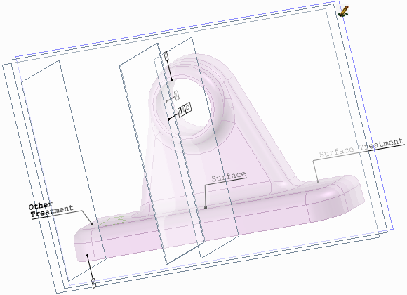
PMI information from a CATIA file
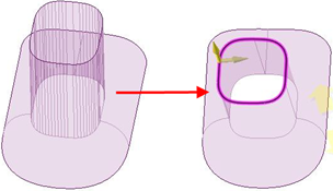
Consolidated multi-segmented curves from a Rhino file
Converter utility
The SpaceClaim Converter is a utility to easily translate between file formats supported by SpaceClaim. It is a separate application, called ‘Converter.exe’, located in the SpaceClaim installation folder.
The Converter is designed to allow you to convert many files from one format to another in a single operation. You can specify files one-by-one and/or choose directories. All files to be converted must be of the same type.
Running the Converter
The Converter is located in the SpaceClaim installation directory. Simply double-click on converter.exe to open the Converter dialog.
Select the files you want to convert. All the files have to be the same format. Build your list using any combination of the commands below.
- Add Files: Opens a dialog to browse to specific files to convert. All files must have the same format. Specify the format by setting the in the Open dialog.
- Add folder: Opens a dialog to browse to a directory containing files to convert. All files matching the File Filter on the Options page will be added.
- Remove: Removes the currently highlighted file(s).
Once you have the list of files to convert, click the Convert button. As the conversion proceeds, you are given the following feedback.
- The file currently being converted is highlighted in Yellow.
- Files that converted successfully are highlighted in Green.
- Files that could not be converted are highlighted in Red. If any file fails to convert, a copy of the file is written to the Failures directory specified on the Options page.
Skip: Click this button to skip (i.e. do not convert) the current file.
Abort: Click this button to cancel the process.
Pause: Click this button to pause the process. When paused, the button switches to Resume.
Converter Options
You need to specify the output file type as well as some other directories used by the Converter. Frequently used conversion settings can be saved and reused.
The Converter options are described below.
- File Filter: When you specify a directory to convert, it may contain many different file types. Since all input files must be the same type, the File Filter specifies which type to convert.
- Recurse: Check this option to include subdirectories.
- TimeOut: This is the maximum time allowed for the conversion. It will be aborted if it exceeds this time limit.
- File Type: This is the output file format. All the input files will be converted to this format. Converted files are written to the same directory as the input file.
- Failures Directory: Any files that fail to convert will be copied to this directory.
- Settings Directory: Converter settings can be saved to an XML file in this folder.
- SpaceClaim directory: This is the directory where SpaceClaim.exe is located. Normally this will be the same directory containing Converter.exe.
- Output directory: The converted files will be saved to this directory.
- Email Recipient(s): The converter will send an email to the specified email addresses. You can select when you want email sent with the following checkboxes.
- Abort if failures exceed: Check this box and enter a percentage of failures. The process aborts when the percentage is exceeded.
- Start separate SpaceClaim for each design: A separate SpaceClaim instance is started for each design to avoid memory exhaustion on large models. This sacrifices speed to save memory. The option is Off by default.
There is a command line switch (for SpaceClaim) to check for add-ins
- CommandLineAddInsOnly will only load add-ins specified in the command line for SpaceClaim
- For example: /CommandLineAddInsOnly=true
- The switch is primarily intended for use with the Converter to limit the add-ins loaded
- The switch can be used to start SpaceClaim without looking for add-ins in the usual locations
© Copyright 2016 SpaceClaim Corporation. All rights reserved.
 IDs for edges, faces, and bodies are now stored within the .scdoc file. Object IDs are preserved when other files are opened or inserted into, and the IDs can also be exported. For example, if you export a design to an analysis company, and they tag geometry with load positions, boundary conditions, and so on, then when you re-import that design, make changes, and re-export to the analysis company, they will not need to recreate their tags on the new design.
 ACIS
ACIS