| SpaceClaim Online Help |
|
Use the Measure tool to display measurements of the edges and faces in your design. Any values displayed on screen are automatically copied into the Clipboard and can be pasted into another document.
The Measure tool is accessible in the Ribbon and from within the Pull and Move tools. Measurement values are selectable only when the tool is invoked within Pull or Move.
You can select units for measurement in the SpaceClaim Units options. You can also modify the Precision and Angular Precision values in the Measure Tool options.
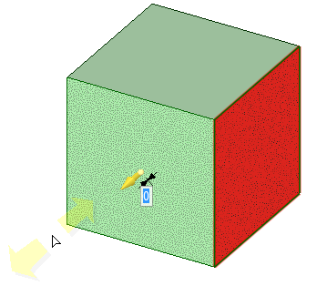
The document origin is displayed by default. You can hold Alt and select the origin or its axes as reference objects, and the distance in that direction (or all three) is displayed.
If you hold Alt and select an origin, then you will see a preview of the X, Y, and Z distance from the origin. This preview changes as you move your mouse over objects in the Design window. If you hold Alt and select any plane, then the preview shows the distance from the point under the mouse to the plane. If you hold Alt and select a line or axis, then the preview shows the distance from the point under the mouse to the line. Clicking on an object sets the dimensions in the results box.
Negative values are displayed for the results when you select an origin and the measurement is negative in the direction of one or more axes.
Click ![]() Measure in the
Measure in the
Mouse over your design to preview the faces and edges eligible for measurement.
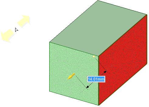
Select points, curves, edges, or faces to display measurement information.
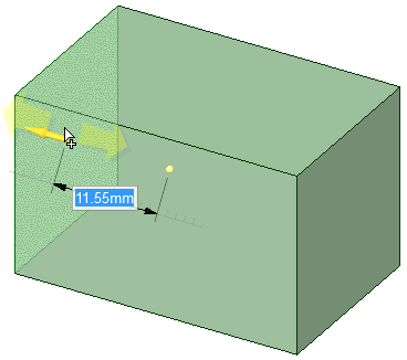
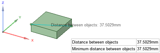
Ctrl + Selecting multiple objects displays measurement between them as appropriate. The value Min. distance between objects displays an exact measurement of the minimum distance between the objects you selected.
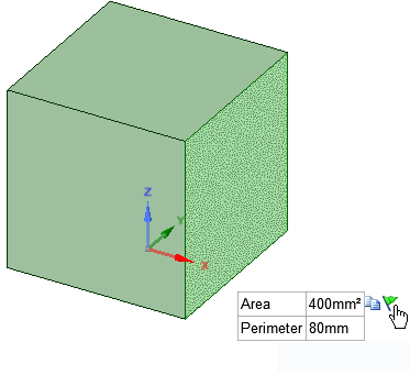
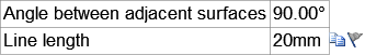
Selecting multiple faces displays their total area.
Triple-click on a body to display its total surface area.
(Optional) Hold Alt and select a reference object.
The reference can be a point, curve, edge, face, plane, axis, or origin.
You can measure to an axis of an origin object.
(Optional) Hover over a measurement value to display the Copy icon. Copy the value to the clipboard for pasting into Notes, etc.
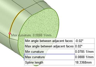
When measuring edges and curves, the Minimum and Maximum Curvature locations are highlighted in the geometry when you hover over the result as shown below.
Selecting a mesh body in the Measure tool reports the total surface area of the body.
Flag groups capture measurements and ensure that unwanted changes are NOT made to the model.
 panel and see that a Flag Group has been created.
In the Groups panel, the group is shown with a Locked icon to indicate that it will prevent modifications. The measurement value is also listed.
The following tool guides help step you through the process. Use the Tab key to cycle through them. As soon as the tool guide switches, the cursor may change to reflect the active guide.
|
|
The Select objects to measure tool guide is active by default. This tool guide allows you to select the object you want to measure. |
|
|
The Select plane or origin tool guide allows you to set the measurement directions by selecting an origin, origin axis, line, or plane. You can hold Alt and select the origin to display the X, Y, and Z coordinates from the origin to the object being measured or between the objects if you select two objects. You can select a plane or origin in the Structure tree |
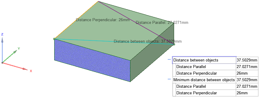
Measuring between two points, with a reference face Alt+selected, so the projected distance is appended to the measurement.
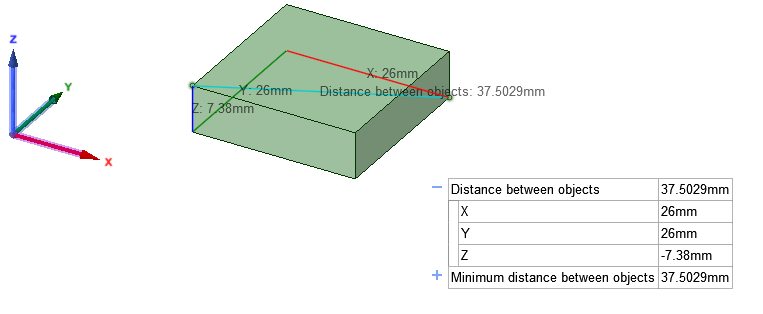
Measuring between two points, but the origin is Alt+selected as a reference, so the X, Y, and Z distances are shown.
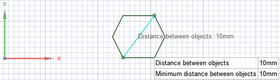
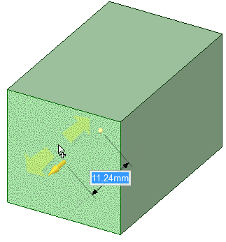
Measuring the distance between two sketch points
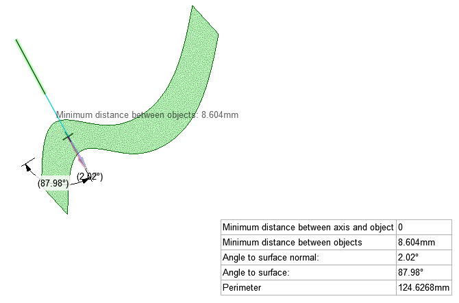
Measuring the angle between a sketch curve and a face. The sketch curve is extended until it intersects the face. Angle to surface normal is the angle between the extended curve and a line that is perpendicular to the surface at the intersection point. Angle to surface is the angle between the extended curve and a plane tangent to the surface at the intersection point.
© Copyright 2016 SpaceClaim Corporation. All rights reserved.
 Flag group example: