
| SpaceClaim Online Help |
|
Use the Polygon tool to draw a polygon with between 3 and 64 sides. You can dimension the location of the axis, the length of the radius, the orientation angle, and set the number of sides as you sketch the polygon.
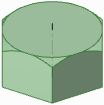
The sides of a sketched polygon maintain their relationship to each other. When you pull a polygon into 3D, faces with a polygon relationship are displayed with a pattern when you select the solid. Changing one face or edge affects all the faces in the relationship.
Click ![]() Polygon in the Sketch group.
Polygon in the Sketch group.
to dimension the polygon based on the diameter of a circle inscribed within the polygon. Uncheck the option to dimension the polygon based on a circumscribed circle.Click to set the center of the polygon.
You can dimension the points relative to other sketch objects.
Drag the mouse to draw the polygon and change its orientation.
The orientation is the polygon's angle relative to the X and Y axis.
You can press Tab and type a number to change the diameter, orientation, or number of sides.
Click to complete the polygon.
The sides of the polygon are all related, and act as one object. When pulled in 3D, the edges and faces of the polygonal solid will also maintain this relationship.
Tip If you trim a polygon sketch with the Trim Away tool, you can drag the original sides of the polygon with the Select tool to recreate the polygon.
Press Tab and type a number while you draw a polygon.
or
In Sketch mode, select the polygon with the Select tool.
Right-click the polygon and select Properties.
Enter a value for the Number Of Sides property.
Polygons can have a minimum of 3 sides, and a maximum of 64 sides.
Right-click a face of the polygon and select Remove Association.
Any changes you make to the face of the polygon will affect only that face.
The following options are available in the Options panel:
|
Use internal radius |
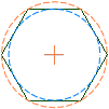
Select this option to dimension the polygon based on the diameter of a circle inscribed within the polygon. Uncheck the option to dimension the polygon based on a circumscribed circle. In the image below, the blue circle is inscribed within the polygon and the orange circle is circumscribed around it. |
|
The following options are available for every sketch tool:
Cartesian dimensions: Select a point in a sketch and then click this option to see Cartesian dimensions from the point. Cartesian dimensions show you the X and Y distances from the point you select. If you don't have a point selected, it shows you the X and Y distances from the origin.
Polar dimensions: Select a point in a sketch and then click this option to see Polar dimensions from the point. Polar dimensions show you an angle and a distance from the point you select. If you don't have a point selected, it shows you the angle and distance from the origin.
Snap to grid: Select this option turn snapping on or off while sketching. The cursor will snap to the minor grid spacing increment while you sketch. The defaults are 1mm for Metric and 0.125in for Imperial units. See Units options to change the minor grid spacing.
Snap to angle: Select this option to turn angle snapping on or off while sketching. The cursor will snap to the angular snap increment while you sketch. The default is 15 degrees. See Snap options to change the angular increment used for snapping.
Create layout curves: The sketch curves are created as layout curves. If you move the design to a drawing sheet, with Sketch mode selected you must select the Create layout curves checkbox again in the Sketch Options group of the Options panel in order to create layout curves on the drawing sheet. See Layout Curves.
Curve Fitter Options: If the Sketch plane passes through a Mesh object, the system will fit curves through the facet points. Lines are displayed green and arcs are displayed blue. The following options apply to the system-generated curves.
Fit curves - Uncheck this option if you do not want the system to fit curves through the points.
Tolerance - Determines how many points will be found, which also determines how many curves will be created. The smaller the tolerance, the more points will be found and the curves will be generated.
Auto-merge - When checked On, the system will merge lines and arcs to form splines. Splines are displayed pink.
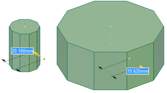
A polygon pulled into a solid maintains the relationships between its sides. In this example, pulling one side pulls all sides of the polygon.
© Copyright 2016 SpaceClaim Corporation. All rights reserved.