
| ANSYS Discovery SpaceClaim |
|
The Gear tool constrains two objects so one of the objects rotates in response to the rotation of the other object. Gear conditions can be created between two cylinders, two cones, a cylinder and a plane, or a cone and a plane.
See the printable Assembly constraints reference chart  for descriptions of all assembly constraints.

|
The Gear tool is enabled when you select appropriate objects that belong to different components. |
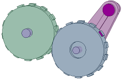
The animated example below shows how anchoring different parts in the assembly affects the behavior of the gears. First we turned the gray component without anchoring it or the rose components. Then we anchored the rose component that is highlighted and turned the gray component. Watch the purple buttons on the rose components to see the difference.
Load GearsExample.scdoc and try it yourself. Try turning on the anchor constraints in the gray or rose components and then use Move to rotate a component.
|
|
If you are using the online version of the help, the model will be downloaded as a zip file. You need to save it to your disk and change the file extension from ".zip" to ".scdoc" |
Click ![]() Gear in the Assembly group on the Design tab.
Gear in the Assembly group on the Design tab.
The constraint is added to the components.
Right-click a Gear condition in the Structure tree and select Reverse Sense to align the components to the opposite side of the alignment plane.
You can also modify the Reversed value to True or False in the Assembly Condition section of the Properties panel.
Select the Gear condition in the Structure tree.
Right-click and select Reverse Rotation Direction.
By default, gears rotate in the opposite direction to the gear turning them. You can reverse this to simulate a belt or chain drive, in which both gears spin in the same direction.

Several examples of gear constraints

Copyright © 2004-2017 ANSYS, Inc. All Rights Reserved. SpaceClaim is a registered trademark of ANSYS, Inc.