| DesignSpark Mechanical Online Help |
|
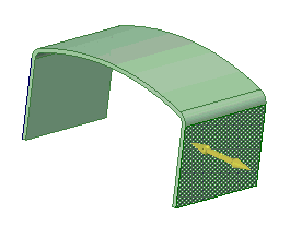
You can dimension every element in your design, from lines in sketches to faces of solids. In DS Mechanical, dimensions are not constraints. Rather, they are tools for precise control during the creation or modification of a design. In DS Mechanical, if you do want to save a dimension with your design, use the Ruler Dimension option when pulling or moving. You can save the ruler dimensions as Groups for later edits.
Whenever dimension fields appear, you can press the spacebar or click on them to enter a value, and press Tab to switch between fields.
You can use mathematical expressions in a dimension.
Press the spacebar (or just type) to enter a value in the highlighted field.
Press Tab to switch between dimension fields.
Repeat step 2 until you have entered all the dimensions.
Press Enter to accept the values and return to sketching.
The dimensions persist until you select another tool or begin drawing another sketch object.

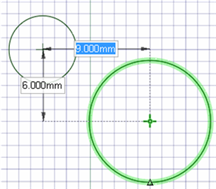
Hover the mouse over the point from which you want to dimension.
Press Shift.
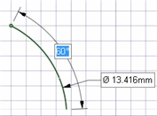
As you move your mouse around the sketch grid, a dimension will appear from the point you indicated to the mouse location.
Press the spacebar (or just type) to enter a value in the highlighted field.
Press Tab to switch between dimension fields.
Repeat step 4 until you have entered all the dimensions.
Press Enter to accept the values and place the point that begins or ends your line.
Click the Select tool.
Select the sketch object you want to change.
Dimension the item's size or location by doing one of the following:
Press the spacebar (or just type) to enter a value in the highlighted field.
Drag the selected item to change its size or location.
Hover over a point in your design and press Shift to dimension between the selected object and that point.
Press Shift while dragging to dimension from the current mouse location.
Select a direction for the move or pull.
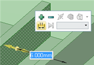
Press the spacebar (or just type) to enter a value in the highlighted field.
Press Tab to switch between dimension fields.
Repeat step 3 until you have entered all the dimensions.
Press Enter to accept the values and move or pull the selected object the distance you entered.
Select the faces or edges whose location you wish to specify.
Select a direction for the dimension.
Select Create Ruler Dimension from the Options panel or right-click and select it from the mini-toolbar.
The start point of the dimension is set as the location of the Pull arrow or Move handle.
Click an object to set the end point of the dimension.
Use the scroll wheel if multiple objects appear at the same point in the Design window.
Enter a value.
Press Enter to accept the value and complete the move or pull.
Press Esc to hide the ruler dimension.
You can make more than one change per ruler dimension.
Select the Move tool and switch to Section mode.
Select the section line (that represents a face) that you want to rotate.
(Optional) Anchor the Move handle to the object around which you want to rotate by dragging the center sphere or using the Anchor tool guide.
Select the rotational axis of the Move handle.
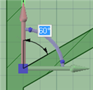
Select Create Ruler Dimension from the Options panel or right-click and select it from the mini-toolbar.
An angular dimension indicator appears from the red linear axis of the Move handle.
Select the end reference for the angular dimension.
Enter a value for the dimension.
© Copyright 2014 Allied Electronics, Inc. All rights reserved.