


 Hide All
You can create a pattern of protrusions or depressions (including slots), points, components, planes, origins, or axes. You can also create patterns of sketch curves. You cannot create a pattern of threads. You can use the Undo button Ctrl+Z or Redo button Ctrl+Y when creating a pattern.
You can also create a pattern from a mix of object types, such as a pattern of holes (faces) and bolts (imported components). In DesignSpark Mechanical, any pattern member can be used to modify the pattern after you create it. If the change cannot be made to all pattern members, the member that cannot change is still part of the pattern. Once you select a Pattern Type, the fill displays to show a pattern preview.
When you select a member of a pattern, you will see fields for the pattern count and distances relative to the member you have selected. Press Tab to move among the dimension and count fields.
-
Icons next to the pattern’s dimensions and counts show which will be changed if you change the value of the highlighted field. The closed lock indicates that a dimension won’t change and the open lock shows you it will change. You can override a lock on a dimension by clicking its icon to toggle it between locked and unlocked.
-
Dimension or count line placement, arrows, and value fields show you how the pattern will change if you change the value of a field.
-
Your selection determines how changes to the distance and count affect the pattern’s position. If you select one member of the pattern, the change is centered on that member. If you select all pattern members, the change is centered on the entire pattern, with the distance between members locked by default. You can control which direction the pattern will grow based on which member you select and which count or distance you change.
-
Changing a pattern count in one direction does not change the distance between pattern members. Instead, the overall distance of the pattern will change. This is indicated by the closed lock icon.
-
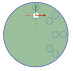
Circular patterns are anchored at the opposite end by default when you move one end.
With a pattern node selected in the Structure tree, you can:
- Change fill pattern parameters in the Layout section of the Properties panel. Changes that you make automatically update the pattern in the design window.
- Right-click and select Lightweight Pattern to toggle a pattern component between a lightweight pattern and regular pattern. When selected, a check mark displays next to the Lightweight Pattern command. This also works with sheet metal components:with a Pattern node selected in the Structure tree, right-click and select Make Lightweight.
- To update lightweight fill patterns to fit the existing geometry of your design, select the lightweight pattern node, then right-click and select Update Pattern.
 |
Patterns of sketch entities and 3D curves are no longer patterns when they change into another form, such as a surface or solid. For example, if you pattern a C-shaped curve, then it will remain a pattern when you switch from sketch mode to 3D mode. But if you close off the curve to make a box before you switch to 3D mode, then the boxes will become surfaces and will no longer be a pattern. |
 To create a one- or two-dimension linear pattern
-
Click the
 Linear tool in the Insert group on the Design tab.
 -
Select a protrusion, depression, body, sketch, points, axes, planes, origins, or 3D curves to be the first member (leader) of the pattern. The Direction tool guide activates.
-
Select a line, edge, axis, or a set of points to set the direction of the pattern.
-
(Optional) Modify the Pattern options in the Options panel.
Pattern Type: One-dimensional or Two-dimensional.
Change X Count, or X Pitch values for One-dimensional
Change X, Y Count, or X, Y Pitch values for Two-dimensional
As you switch between pattern types, or change pattern values, the pattern preview displays your changes in blue.
- Select the Create Pattern tool guide, or press Enter, to complete the pattern.
The image below shows the preview for a two-dimensional pattern. For one-dimensional, only the X-direction is displayed. Clicking the arrows flips their direction 180-degrees.
For through-all cuts, the preview is on the plane closest to the direction reference. For blind cuts, the preview is on the face of the selected pattern leader.
You can also create one-dimensional linear patterns on cylindrical faces as long as the pattern direction is either the cylinders axis or parallel to the axis.


To create a pattern of a pattern
Follow the steps for the linear pattern, but select a member of a linear pattern as the first member of the pattern.
-
Click the
 Circular tool in the Insert group on the Design tab.
 -
Select a protrusion, depression, body, sketch, points, axes, planes, origins, or 3D curves to be the first member (leader) of the pattern. The Direction tool guide activates.
-
Select a line, edge, axis, or a set of points to set the direction of the pattern.
-
(Optional) Modify the Pattern options in the Options panel.
Pattern Type: One-dimensional or Two-dimensional.
Change Circular Count, or Angle values for One-dimensional.
Change Circular Count, Angle, Linear Count, or Linear Pitch values for Two-dimensional.
Note that a Circular Count of one will create a single radial pattern.
As you switch between pattern types, or change pattern values, the pattern preview displays your changes in blue.
-
Select the Create Pattern tool guide, or press Enter, to complete the pattern.
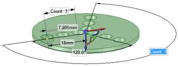
The image below shows the preview for a two-dimensional pattern. For one-dimensional, only the Angular direction is displayed. Clicking the arrows flips their direction 180-degrees.
You can create circular patterns on cylindrical faces, both around the face and along the axis.
-
Click the
 Fill tool in the Insert group on the Design tab.
 -
Select a protrusion, depression, sketch, points, axes, planes, origins, or 3D curves to be the first member (leader) of the pattern. The Direction tool guide activates.
-
Select a line, edge, axis, or a set of points to set the direction of the pattern.
-
Modify the options in the Options panel
Pattern Type: Grid or Offset
Modify the X Spacing or Y Spacing
Modify the Margin values. A dashed orange boundary line displays the pattern's marginal boundary.
As you switch between pattern types, or change pattern values, the pattern preview displays your changes in blue.
-
Select the Create Pattern tool guide, or press Enter, to complete the pattern.
To create a radial circular pattern
-
Select all radial pattern members.
-
Click the
 Move tool.
 -
Re-anchor the Move tool on the circular axis.
-
Select the Create patterns check box in the Options panel.
-
Drag the radial pattern to form a circular pattern.
To create a pattern of points along an edge
-
Select a point to be the first member of the pattern.
-
Click the
Move tool. -
Select the Create patterns check box in the Options panel.
-
Click the Move Along Trajectory tool guide.
-
Click one of the edges that connects to the vertex.
-
Click the Move handle axis.
-
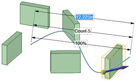
Drag to create the end pattern member and create the pattern.
-
Press Tab to change the count, length, and percent fields to edit the pattern of points.
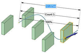
All points are associated with the edge, so that when the edge changes, the points also change as shown in the example below.
To edit a pattern's properties
-
Select one pattern member to display the pattern count and dimensions.
-
Edit the pattern's properties.
Press Tab to switch between the fields.
Click the lock icon to lock or unlock a value.
-
Press Enter.
The result of editing the count and spacing is relative to the member of the pattern you select.
|
To quickly increase or decrease the number of pattern members, press Tab until the count field is highlighted, then hold the Alt key while you press the up or down arrow. |
-
Click the
Move tool. -
Select a pattern member to move a linear pattern or the pattern axis to move a circular or arc pattern.
-
Move the pattern member with the Move handle.
If you move an interior member of a pattern and it is not anchored, all the pattern members move:

If you move a member at one end of a pattern, the member at the opposite end is anchored and the pattern is skewed:

If you anchor a different member than the member opposite the direction you are moving, Move skews the pattern.
If you have a linear pattern in a radial direction and you move an interior member without setting an anchor, then the entire pattern shifts in the selected direction
Use the Up To tool guide to move a pattern member up to another face or edge. Pattern dimensions (such as Count and Length) display as expected.
To move a radial pattern in a linear direction
-
Click the
Move tool. -
Right-click a pattern member and click Select > All Pattern Members.
-
Select the Direction tool guide.
-
Click an object to set the direction of the move.
-
Drag the pattern.
To adjust pattern distance or spacing
-
Click
 Select or Move in the Edit group on the Design tab.
 -
Select a pattern member.
This member will serve as the anchor, and other pattern members will move relative to this member.
-
Press Tab until the field you want to change is highlighted:
-
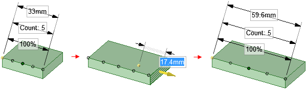
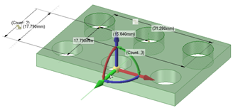
Distance: This field is the overall distance of the pattern. The pattern member you select is anchored, and the length will change relative to this member. The arrows indicate the direction of change. You can see this field at the top of the image below.
-
Spacing: This field is the spacing between pattern members. This field has arrows in both directions and is located between two pattern members. The field is highlighted in blue in the image below.
-
Radial patterns: If you select a member of a radial pattern, you can change the angle between pattern members and the distance from the pattern members to the center of the pattern.
-
-
Type a new distance or angle and press Enter.
The spacing between all pattern members will change.

To remove a pattern member from the pattern
Right-click the face of the pattern member and select Unpattern Member. Doing this makes the member independent, so changes to the feature won't propagate to the pattern.
-
Select a pattern or pattern member in the Design window.
-
Click the Groups tab in the Structure panel.
-
Click Create Group.
A group is created that displays the number of members in the pattern. You can click on this group to select the pattern and change its parameters in the Design window.
To assemble components on a pattern
You can assemble a component with a pattern member, then propagate the component to all of the pattern members. The component will be copied and assembled to each pattern member.

To create a pattern along a trajectory
-
Click
Move tool. -
Select the object you want to pattern.
- Click the Move Along Trajectory tool guide and select the curve to use as a trajectory.
You can also hold Alt and double-click the curve.
- Check Create Patterns in the Move options.
- Pull the trajectory arrow.
- Release the mouse button to display pattern dimensioning options, then enter values by tabbing through the options.
- (Optional) Check Maintain Orientation in the Move options to keep the patterned objects in the same orientation as the original object.
Pattern along a trajectory without maintaining orientation.
Pattern along a trajectory with orientation maintained.
Examples
Rectangular pattern
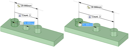
Changing spacing between pattern members changes the pattern's overall length when the length field isn't locked.

A pattern of sketch objects is no longer a pattern when you switch to 3D mode and the sketched objects are converted to surfaces.

Sketch curve patterns can propagate in two dimensions. The pattern above contains three squares in the X direction and two squares in the Y direction.