


 Hide All
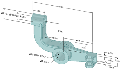
Use the Dimension tool to add a measurement to your design, drawing sheet, or 3D markup.
You can use annotation dimensions with the Pull and Move tools to change your design. See Driving modifications with annotation dimensions.
An annotation plane cannot be moved to a sub-component after you add dimensions because the references would be lost.
You can enable dual dimensions, which will display each dimension in both Metric and Imperial units. See Units options.
 To create a dimension annotation
-
Click the arrow under the
 Dimension tool and select Dimension.
 -
If you are creating a dimension in 3D, click a face to create an annotation plane on which to place the dimension.
Mouse over the faces of your design to preview the eligible annotation planes. (In Sketch and Section mode, the sketch grid defines the annotation plane.) If multiple objects occur at your cursor location, use the scroll wheel or arrow keys to highlight each one.
To create an annotation plane for a cylindrical face, select the cylinder's axis.
If you need to change the annotation plane, right-click and click Select New Annotation Plane from the context menu and select a new annotation plane.
-
Click an edge or face.
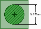
Where you click on a circle determines whether you will measure from the circle's center, near, or far edge. To select the center click the top, bottom, left, or right side of the circle.
-
Mouse over your design to preview the possible dimensions.
-
Click a second object if you want to dimension between two objects.
-
(Optional) Select a dimension orientation in the Options panel. You can also select the orientation for the first and second reference.
-
Click to create the dimension.
To create an arc length dimension
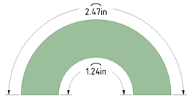
Two methods:
- Hold the Ctrl key down and click on the arc.
- Click the arc first and hold the Ctrl key down while dragging the dimension.
-
Click the arrow under
Dimension in the Annotation group on the Detailing tab and select  Ordinate Dimensions.
 -
If you are creating a dimension in 3D, click a face to create the plane on which to place the dimension.
Mouse over the faces of your design to preview the eligible annotation planes. (In Sketch and Section mode, the sketch grid defines the annotation plane.) If multiple objects occur at your cursor location, use the scroll wheel or arrow keys to highlight each one.
To create an annotation plane for a cylindrical face, select the cylinder's axis.
If you need to change the annotation plane, right-click and click Select New Annotation Plane from the context menu. Then right-click the new place and click Set As Annotation Plane.
-
Click a line or edge to set the baseline dimension.
You can use an existing extension line as a dimensioning reference. An extension line is the line that connects the point to the dimension text. If you select an extension line, the baseline dimension for the extension line's dimension is used.
-
Mouse over the face to see all the possible dimensions.
-
Click a point to place the dimension line.
If you select a face, all of the possible ordinate dimensions will be created.
You can click multiple points to use the same baseline for those dimensions.
The baseline dimension (0) is displayed or hidden based on which detailing standard is selected in the Detailing options.
Automatic jog points are included if ordinate dimensions are too closely spaced. This helps make them easier to read.
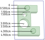
Using an angled baseline
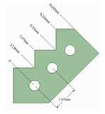
First, establish a simple, oriented dimension. Then use one of the witness lines to set the baseline and orientation of the ordinate dimensions.
In the example above, the leftmost witness line of the existing circle-to-circle dimension was selected to define the baseline.
-
Click
Dimension in the Annotation group on the Detailing tab. -
Click the Select bodies tool guide on the right side of the Design window.
-
Select the solid body or bodies you want to dimension:
-
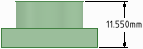
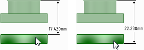
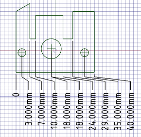
If you select a single body, then the maximum horizontal or vertical dimension is created, as shown below.
-
If you select more than one body, then the dimension is created for both solids and is anchored on the side closest to where you click on the solid. You must click on the Select bodies tool guide before you select each solid, so you click the tool guide and select the first part, then click the tool guide again and select the second part.
In both of the examples below, the upper part was selected near its top. The lower part was selected near its top in the example on the left and near its bottom in the example on the right. The mouse arrows indicate where the lower part was selected. You will see a preview of the dimension when you click the tool guide and hover over the second part.
-
If you create the dimension in a section view of a drawing sheet, then the dimension is created on the extents of the body that is visible in the section plane, as shown below.
-
To edit a dimension annotation
-
Select the dimension annotation to move, size, or rotate it.
To move the dimension note, mouse over the edge of the box with the Select tool until the cursor changes to
 , then drag the note.
To size the box that contains the dimension note, drag the handles of the note box (the white circles).
-
Select the text of the note to reformat it.
-
(Optional) Right-click the dimension and select text formatting options from the mini-toolbar.
Click
 to select a tolerance format, then edit the text of the tolerance.
Click
 to insert a field. You can select a field type and format from the Insert Field window.
Select from the
 drop-down to insert a symbol.
 -
Click an arrowhead to cycle through alternative leader styles.
You can also right-click an arrowhead and select Arrow Style to select a style for that arrowhead, or select the arrowhead, then select the style for the head in the Properties panel.
-
Click the note leaders to modify them.
You can right-click a leader and select Add Jog Point to add a new point.
-
To change the distance between a dimension extension line and its reference point on the object, click on the extension line, then hover over the end closest to the object. Drag the red dot to change its distance from the object.
If you cant' see the extension line, hover over the end of the dimension leader, where the line would be. You will see two red dots that you can drag:
-
Modify the dimension note properties in the Properties panel. Modify the:
-
Arrow Length and Width properties to set the length and width of the arrowheads
-
Measurement property to change the measurement type. For example, you may want to display the radius of a hole instead of the diameter.
- Precision property to change the number of decimal places.
-
Upper Limit, Lower Limit, and Type of tolerance property to change the format of the dimension and enter upper and lower tolerance values.
-
- To fit a dimension within the text box
- RMB Click on the note and open the Autofit drop-down menu.
- Choose one of the following options:
- Do not autofit: The text box adjusts to the size of the text and grows as you type. There is no blank space around the note and making the text larger or smaller adjusts the box accordingly.
- Resize text height on overflow: The text always fits the width of the box. If you make the box wider, text from the second line will move up to the first line.
- Shrink text on overflow: The text adjusts uniformly (width and height) and scales to fit in the text box.
- Shrink text horizontally on overflow: The width of the text changes but the height remains the same.
To display the annotation and hide the plane
-
Create two layers, one for notes, and one for the annotation planes.
-
Place the note on one layer and the annotation plane on another layer.
-
Turn off the visibility of the layer that contains the annotation plane.
- Select multiple dimensions.
- In the RMB menu, choose from the following:
- Align Lefts - Align the left side of each dimension.
- Align Centers - Vertically align the center of each dimension.
- Align Rights - Align the right side of each dimension.
- Align Top Lines - Align the bottom of the first line of text in each dimension.
- Align Middles - Horizontally align the middle of each dimension.
- Align Bottom Lines - Align the bottom of the last line of text in each dimension.
- Make Same width - Make each dimension the same width based on the first note selected. Some text may be scaled accordingly.
- Make Same Height - Make each dimension the same height based on the first note selected. Some text may be scaled accordingly.
- Make Same Size - Make each dimension the same size (height and width) based on the first note selected. Some text may be scaled accordingly.
- Distribute Horizontally - The space between each dimension is distributed evenly horizontally.
- Distribute Vertically -The space between each dimension is distributed evenly vertically.
- Remove Horizontal Spacing - The even horizontal spacing is removed and any significant overlap is equalized.
- Remove Vertical Spacing - The even vertical spacing is removed and any significant overlap is equalized.
Any notes rotated differently are not affected by the above commands.
To display dimensions for an annotation plane
Right-click an annotation plane and select:
- Show all dimensions to display dimensions on all annotation planes.
- Show dimensions to display the dimensions for only the annotation plane you right-clicked.
Examples
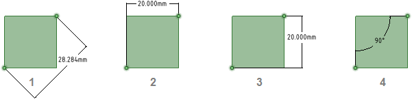
Annotations with orientation changed in the Options panel
-
Dimension Orientation set to Aligned
-
Dimension Orientation set to Horizontal
-
Dimension Orientation set to Vertical
-
1st Reference Orientation set to Horizontal, 2nd Reference Orientation set to Vertical
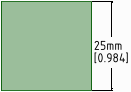
A dimension annotation with dual dimensions enabled in the Units options
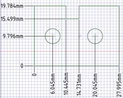
Ordinate dimension annotations
Ordinate dimensions for a planar face
Automatic jog points with closely spaced ordinate dimensions