| DesignSpark Mechanical Online Help |
|
The Align tool enables if a model is loaded, and it aligns two points, lines, planes, origins, or combination of these elements. If you select a cylindrical or conical face, then the axis is aligned. If you select a spherical face, then the center point is aligned. You can define a ball joint assembly condition using Align by selecting the face of the ball and then the face of the socket. The ball rotates within the socket no matter where you place the move handle on the ball part.
See the printable Assembly constraints reference chart  for descriptions of all assembly constraints.

|
You can use the Align tool to move objects without assigning assembly conditions. If the objects belong to different components, uncheck Create conditions in the Assembly |
Click ![]() Align in the Assembly
Align in the Assembly group on the Design tab.
The Align tool guide is enabled by default.
Select an edge or face of the component that you want to move.
You can Ctrl-click to select multiple objects.
The Reference tool guide is enabled.
Select an edge or face of the component that you want to remain stationary.
The components align. You can control the alignment animation with the Animate Full Pull Advanced DS Mechanical option.
The constraint is added to the components in the Structure tree.
Use the Select tool to click the component you want to move, then Ctrl+click the component you want to remain stationary. Then click ![]() Align in the Assembly group on the Design tab.
Align in the Assembly group on the Design tab.
Right-click an Align condition in the Structure tree and select Reverse Sense to align the components to the opposite side of the alignment plane.
You can also modify the Reversed value to True or False in the Assembly Condition section of the Properties panel.

Select the Align condition in the Structure tree.
Change the angle value in the Offset property in the Properties Panel.
Click ![]() Align in the Assembly group on the Design tab.
Align in the Assembly group on the Design tab.
The Align tool guide is enabled by default.
Uncheck Create conditions in the Options panel.
Select an edge or face of the object that you want to move.
You can Ctrl+click to select multiple objects.
The Reference tool guide is enabled.
Select an edge or face of the object that you want to remain stationary.
The components align. You can control the alignment animation with the Animate Full Pull Advanced DS Mechanical option.
The following tool guides help step you through the process. Use the Tab key to cycle through them. As soon as the tool guide switches, the cursor may change to reflect the active guide.
|
|
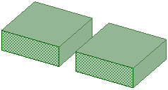
The Align tool guide allows you to select the component to move. |
|
|
The Reference tool guide allows you to select the component to remain stationary. |
Clicking on the Align assembly condition in the Structure tree highlights the faces.
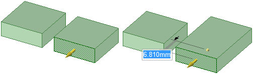
Pulling one face of the aligned pair changes one object and moves the other.
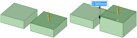
Pulling an adjacent face has no affect on the aligned pair.
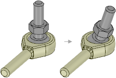
Defining a ball socket using align.
© Copyright 2018 Allied Electronics, Inc. All rights reserved.