| DesignSpark Mechanical Online Help |
|
Set the startup options, interface, application performance (speed vs. graphics quality), and customize the tools that are displayed while you are working with your design.
Select DS Mechanical Options from the File menu to display the DS Mechanical Options window.
Click Color in the navigation panel on the left.
Modify the options on the page.
Click OK to save all your changes and close the window.
Rendering quality: Select a value from 1 to 10, where 1 is the lowest quality and 10 is the highest quality. Select a low number to increase the speed of the application; select a high number to increase the quality of the graphics. Increasing graphics quality may lower the DS Mechanical's responsiveness to actions in the Design window. If you notice a delay when working with your design, modify this option to increase application speed. Within Rendering Quality, you can also choose Custom, which allows you to set your own values for Surface tolerance, Normal tolerance, and Max edge length.
Surface tolerance is the distance between Facet Edges and the actual surface. It’s a measure of the distance between the facets and the real geometry.
Normal tolerance is the angle between adjacent Facet Normals. It’s a measure of the smoothness of the faceting.
Max edge length sets a limit for Facet size. Smaller Facets match the real geometry better than larger ones.
Note: You can also customize faceting on individual bodies in the Properties panel with the new Tessellation Quality Level setting.
Note: Values above 7 appear in red since selecting these values will greatly impact performance. It is strongly suggested that you do not select a value greater than 7.
Images below show the differences between a 7 value (left) and 10 value (right).
Note: Images show a sub-millimeter view of a meters-long part.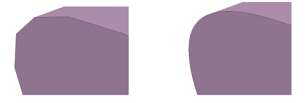
Note: Recalculate Rendering is disabled when you change the Rendering quality. To re-enable Recalculate Rendering, click Ok or Cancel in DS Mechanical Options.
Anti-aliasing: The amount of smoothing applied to text, edges, and face boundaries in the Design window. This option appears only if your graphics card supports anti-aliasing.
Recalculate Rendering: Select this option to update the 3D display in the Design window.
Sometimes when you're modifying a model, the graphics can become misaligned. In the example below, increasing the height of the cylinder has caused it to become misaligned at the base. The actual geometry is still correct, but the selected rendering quality was too low to maintain the visual appearance in the Design window.
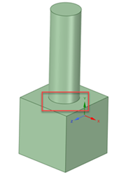

In DS Mechanical Options in the Popular section, you can click Recalculate Rendering to bring the model back into alignment visually in the Design window.
Multi-threaded faceting: Select this option to calculate faceting in parallel to improve performance.
Show splash screen: Select this option to display the splash screen when you start DS Mechanical.
Show welcome screen: Select this option to display the Welcome window with links to tutorials, training videos, and other support resources when you start DS Mechanical.
Check for software updates: Select this option to use your internet connection to check for updates each time you start DS Mechanical.
Report performance information to DS Mechanical: Select this option to share data, based on performance, to help improve product reliability, performance and functionality. Shared data does not contain any model or design information.
Show tooltips: Select this option to display hints when you hover over tools, tool guides, and other icons. They briefly explain what will happen when you select the tool and provide some hints on how to use the tool.
Show popup messages in status bar: ON by default. Select this option to display popup messages in the status bar area (the lower left corner of the DS Mechanical window). These messages provide hints and feedback while you work in DS Mechanical.
Show popup progress messages: ON by default. Select this option to display progress messages when importing files or using the Volume Extract tool.
Show tool KeyTips: Select this option to enable keyboard shortcuts. Pressing and releasing the Alt will display shortcuts that can be used to access the Quick Access toolbar, the Ribbon groups, and the tools in the Ribbon groups. You can also use Key Tips to open files from the Recent Documents list as follows:
Show scroll bars: Check this option ON to add scroll bars to the Design window for panning left-right and up-down.
Tool Guide position: Select Left, Right, Top, Bottom, or Not Shown.
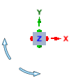
Show view orientation in design window: Default is OFF. When selected, this option displays a view orientation gizmo, as shown below, in the design window. You can click a linear gizmo arrow to rotate the design to a new orientation in 3D, or a rotational arrow to rotate the design in 90-degree increments in the plane of the screen.
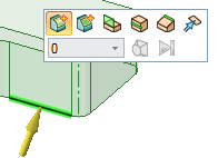
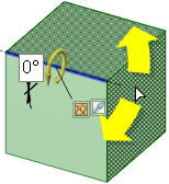
Show mini-toolbar on selection: Select this option to display a small toolbar near your cursor when you right-click. The contents of the mini-toolbar depend on the tool you are using. You can click or scroll the middle mouse button to hide the mini-toolbar, and it fades as you move the mouse away from it. The mini-toolbar is shown in the image below.
Show radial menu: Allows you to use the radial menu to change select modes while other tools are active, and gives you quick access to the Pull, Move, Fill, and Combine tools. If you select this option, you can select one or both of the following methods to open the radial menu:
Show cursor arrows: Select this option to display arrows next to your cursor that indicate the directions in which you can move your mouse to edit the selected object. The arrows also convey the change in size that will occur if you pull in that direction.
Arrow transparency: Adjust the slider to control the transparency of the cursor arrows. Move the slider to the right to make the arrows more opaque; move it to the right to make them more transparent. The arrows are set to opaque in the image below.
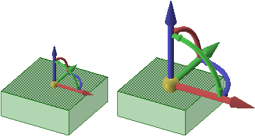
Move handle size: Move the slider to increase or decrease the size of the Move handle relative to the size of the Design window, as shown in the image below.
Grid guide: Change the position and size of the toolbar displayed for the sketch grid. You can set the Position (Bottom, or Corner), and the Size (Large, or Small). The defaults are Bottom and Large.
© Copyright 2018 Allied Electronics, Inc. All rights reserved.