| DesignSpark Mechanical Online Help |
|
As you develop a model, the Clip with Volume tool enables you to create a spherical clip volume around an object so that you can selectively isolate a specific region, element, or section of a design.
Using Clip with Volume can be particularly helpful when you need to closely view and work on a specific feature of interest within a complex model. For example, after isolating a design area, you can use the Repair > Missing Faces tool to help detect and fix missing faces on a body.
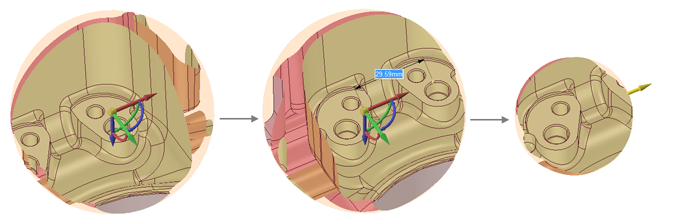
Rotate and zoom in to your model to locate the model element or area you want to view.
With nothing selected, right mouse click and select Clip with Volume > Set.
This action clips the viewable and selectable geometry by the radius of a virtual sphere.
Hover over the center of the element you want to view and then Click+drag to create your spherical clip volume.
Release the mouse.
The area you selected to preview magnifies and displays in a sphere as clipped, or isolated, from the rest of the model.
Right mouse click and select Clip with Volume > Select.
This selects the virtual spherical surface of the area.
In the Properties panel, you can change the following:
with Volume > Set Using Selection.
This sets the virtual sphere's extents based on the current selection.
Hover over the area to identify all of the various design elements.
To re-display your design with no clipping, right mouse click and select Clip with Volume > Clear.
Use the Move option in the Clipped Volume menu to move the clipped volume frame to a different area of the model, or the Resize option to adjust the size of the Clipped volume frame. See images below.
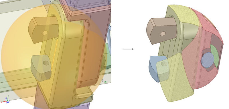
Use the Extract Geometry option to cap off clipped boundaries according to Clip Type (Spherical volume or by Planes). The result is shown in the Structure Tree as a Geometry Snapshot.
For intersections with Solids, Extract Geometry creates a Geometry Snapshot that is a solid.
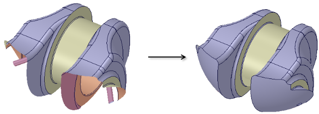
For intersections with Surface models, Extract Geometry also creates a Geometry Snapshot, but displays the surfaces with a more opaque, solid look.
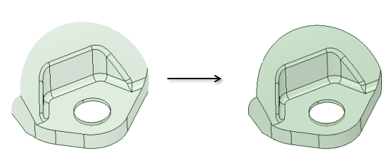
For intersections with Mid-surface models, or any surface with an assigned thickness, Extract Geometry creates a Geometry Snapshot with the assigned thickness.
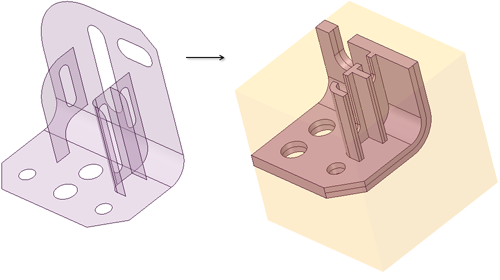
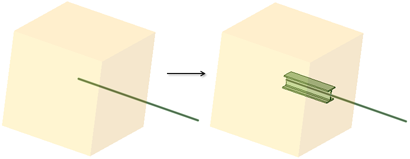
For Beams, Extract Geometry creates a Geometry Snapshot showing their actual geometry.
Extract Geometry also creates a Named Selections group that shows the faces created at the boundary.
© Copyright 2018 Allied Electronics, Inc. All rights reserved.