|
DesignSpark Mechanical Online Help
|

|
You are here: Working with DesignSpark Mechanical documents > Importing and exporting
Importing and exporting
Use the Open command to open files created in any supported format. Use the Save As command to export parts, assemblies, and drawing sheetsto formats read by other applications. Your license type determines which of these actions are supported.
If you work frequently with non-DS Mechanical files, we recommend that you set your file options to optimize the importing and exporting process for your needs.
IDs for edges, faces, and bodies are now stored within the .rsdoc file. IDs are preserved when other files are opened or inserted into, and the IDs can also be exported. For example, if you export a design to an analysis company, and they tag geometry with load positions, boundary conditions, and so on, then when you re-import that design, make changes, and re-export to the analysis company, they will not need to recreate their tags on the new design.
If you import a file and it fails, the reason for the failure is reported in the Status Log on the lower right edge of the window.
To import a design
-
Select Open from the File menu or click  in the Quick Access toolbar.
Depending on the selected file type, additional elements appear in the Open window. For descriptions of these options or to set their default values, click Options.
-
Select Check Geometry to run the geometry check after the file is opened or imported. See Checking geometry.
-
Navigate to and select the file you want to open or insert.
If you are opening a file, it is displayed in a new . If you are inserting a file, it appears as an external component within the active design.
If there is an invalid character in the path of a file you are trying to open or insert, that character is replaced with a valid character to avoid errors.
Click Stop in the status bar to cancel an import while it is in progress.
The name of the imported file is displayed in the Status Log when it is successful.
Expand the sections below for information about a specific file format.
To export a design
-
Select Save as from the File menu.
You can also press F12 or Ctrl+Shift+S.
Your design must be saved as a document before you can export it in another format.
-
Select a file type from the Save as type drop-down.
-
Depending on the selected file type, additional options appear in the Save As window:
-
Save as copy if you want to save copies of external components referenced by the design with new names or replace external components with other external components. You must click Resources to do this.
-
References to display all the external components referenced by the file. Select one or more external components and click Browse to rename or replace the components.
-
Override Units is available when you export some file types. Select the units from the list.
-
Options to also set your default export options for the selected file type.
-
Improve data on export to clean up imprinted edges and split curves when you export data.
-
Units Depends on file type
-
Choose a standard view
-
Version Depends on file type
-
Export part manufacturing information (JT)
-
Protocol: For files can be 203, 214, or 242.
-
Image size (pixels): For Bitmap, GIF, JPEG, PNG, TIFF files opens Image Size dialog
Hidden lines are exported with the default line weight. Components maintain their mirror relationships when they are exported.
For STL and files, you can select which version or protocol to save as. You can also set your default export options by clicking Options.
You can save documents that only contain sketch curves to IGES and formats. You can import and export free points for PDF, IGES, and formats.
Imported designs with identical file names are given unique file names when you save your design. For example, if you imported name.prt and name.asm, these files are saved as name.rsdoc and name2.rsdoc.
Expand the sections below for information about a specific file format.
-
Browse to a folder and type a file name in the dialog.
-
Click Save.

|
Import and Export are separate operations and not symmetric (i.e. one is not the opposite of the other). Therefore, exporting an scdoc to another format and then importing back into DS Mechanical presents a small risk of losing some data. |
Import: Supported File Types
IDF 3.0 and IDF 4.0
open IDF and PADS files
.idf, emn, .idb
-
Most content within IDF 4.0 files is supported.
-
of panels and boards, cutouts, filled areas, keep-ins, materials, panels and everything related, sublayouts, and thermal models are not supported.
-
Open IDF and PAD files
- IDF files can be synchronized with the imported model.
- Select any geometry in the model and use RMB > Update IDF to update the IDF file based on component operations performed in the model (e.g. moved components).
- The current DS Mechanical document must have been created by importing an IDF file.
- The source IDF file must be present on disk at its original location.
- A new IDF file is written that contains the updated information.
- The new file can be read back into the originating ECAD system to update the components.
versions up to 5.3
parts, assemblies
.igs, .iges
- Curves and Colors are supported on import.
curves (insert only)
.txt
-
A spline curve is created by default or if the option Polyline=False is used. If the option Polyline=True is used, then the points are connected by straight line segments.
-
By default, 2D curves are created. When specifying 2D curves, the first column of the data points must be an integer and gives the height of the plane of one of the curves. The beginning of a new curve is specified by changing this height from one line to the next. If option 3D=True is used, the curves can be 3D
-
Use the Fit keyword to specify whether Fitting or Interpolation is used.
Fit=True uses Fitting. Fitting creates a curve that "Fits" the data points using a specified tolerance. The curve may not pass exactly through all points and the distance from the curve to the point will be within the tolerance.
Use the Fittol keyword when Fit=Trueto specify the Fitting tolerance in model units. For example Fittol=1.0e-2
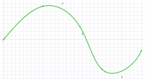
The curve below uses Fitting (i.e. Fit=true). A large tolerance (fittol=2.0) is used to exaggerate the fact that the curve does not pass through the points but only gets within the specified tolerance.
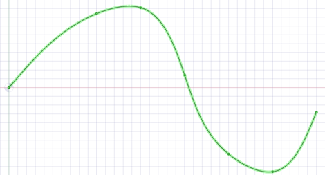
Fit=False uses Interpolation. Interpolation requires that the curve pass exactly through all of the points. An interpolation method is used to build a continuous curve through all of the points.
The curve below is interpolated (i.e. Fit=False). There are seven points in the file and the curve passes exactly through each one.
-
Multiple curves are separated by blank lines.
-
You can import point curve text files that contain single-point curves, which will be created as points.
-
-curve text files opened or inserted in display a closed curve when the file has a repeated value.
-
Curves can be imported to coordinate systems or other geometry like other imported objects.
-
-curve text files with columns separated by commas can be opened or inserted in . This feature allows you to import any comma-separated value file into .
-
If there is an error reading the input text file, a message will appear with the line number of the error in parentheses followed by the text appearing on that line.
-
The following example shows the contents of a point curve text file on the left and the 3D curves it creates on the right:
-
that the point coordinates are (Z, X, Y).
-
For example (1, 2, 3) is (Z=1, X=2, Y=3).
|
3d=true
polyline=false
1 0 0
1 0 1
1 1 0
1 1 1
2 0 1
2 1 0
3 0 0
3 0 1
3 1 0
|
|
Keywords:
- polyline=false - spline curves are created.
- polyline=true - straight lines are created.
- 3d=true - 3D curves are created.
- 3d=false - curves are two-dimensional. This is also the case if the option is not set.
- fit=true - use Fitting.
- Fitting finds the "Best Fit" through the points.
- Does not require the curve to pass through all of the points
- fit=false - use Interpolation.
- Interpolation forces the curve to pass through all the points in the file.
- fittol=1.0e-2 - Fitting tolerance in the units used in the file.
The blank line after the first set of coordinates indicates that the next set of coordinates is a new curve.
You can copy the file contents above and paste them into a text file, then use  Insert File to try it yourself.
V2015.0 SP0
parts, assemblies
.rsdoc
Up to SketchUp 8, V2013, V2014, V2018
parts, assemblies
.skp
AP203, AP214, AP242 (geometry)
parts, assemblies
.stp, .step
When you import assemblies from one file, select the Create multiple documents when importing assemblies file option if you want the assemblies to remain in one file instead of being split into multiple files, one for each internal component.
- import and export is supported
- import is supported
- License is required
Facets or Solids
parts, assemblies
.stl
-
When exporting STL files, the output is set to Binary by default.
-
STL files can include polyface meshes, and they can be imported as lightweight objects. Polyface meshes are imported as solids.
-
When saving as an ., the quality is based your graphics quality setting. We recommend setting the option to enable the highest possible graphics quality if you want your design to be useful as an rapid prototype for form, fit, and function purposes.
-
You can import an as a solid, if it has multiple planar areas that can be merged into one planar face.
-
You can import an as a and export it as another . This makes it possible to import multiple STL files into a document and then export everything as a single .
files (insert only) with proper codec(s) required for all but WMV and AVI
.wmv, .avi, .flv, .mkv, .mov, .mp4, .mpg, mpeg, .ogm, .vob
See Inserting a video
Facets
parts, assemblies
.obj
Export: Supported File Formats
Facets, Geometry (PRC B-Rep), curves
parts and assemblies
.pdf
- 32-bit and 64-bit platforms are supported.
- Color information is exported for 3D PDFs.
- Supports B-Rep import and export
- Mesh-only .scdoc's can be exported to PDF.
- No Adobe Acrobat required for B-Rep import and export, 32bit and 64bit platforms supported, Adobe Acrobat X Pro is not supported
- SCDM optional module for 3D PDF is available
2D Print to or save drawings only
.pdf
- 32-bit and 64-bit platforms are supported.
V1.0
3D - parts, assemblies
.amf
-
Export also supports compressed AMF
-
The following are supported for export:
-
Geometry
-
and face colors
-
material
-
Textures
-
Lightweight components
-
structure tree
-
Export is supported by the Converter.
R12 to 14, 2000, 2004, 2007, 2010, 2013, 2018
Export as 2D snapshot and Solids ( V7 format)
.dxf
MS Office 2003, 2007, 2013
.xls, .xlsx
- If MS Office is installed
- Table export: Web page (.htm; .html), XML document (.xml), CSV file (.csv)
parts, assemblies
.glb
- Binary glTF (GL Transmission Format) for scene graphics export.
- Supported features include solid bodies, surface bodies, faceted bodies, lightweight components, and curves.
- Includes graphics information such as body and face color, body finish (High/Medium/Low Gloss), and camera position.
- Known limitations include faces with texture or hatched, brushed, and metallic render styles.
- Use caution with proprietary models since the data is copied to web location.
V5.3, JAMA-IS, Types: 186, 144, 143
parts, assemblies
.igs, .iges
parts, assemblies, drawing sheets (export as 2D snapshot)
.bmp, .gif, .jpg, .png, .tif
On export, you can specify the image size in pixels or percent of full size.
When saving a drawing as an image you can specify Use Scene extents or Use Sheet extents. Scene extents includes gray borders around the drawing to fill the size of the entire scene. Sheet extents only includes what is within the sheet boundary.
See Inserting an image
MS Office 2003, 2007, 2013
- If MS Office is installed
V3.0 to V8.0, V2013 to V2018
parts, assemblies SketchUp
.skp
AP203, AP214, AP242 (geometry)
parts, assemblies
.stp, .step
When you import assemblies from one file, select the Create multiple documents when importing assemblies file option if you want the assemblies to remain in one file instead of being split into multiple files, one for each internal component.
parts, assemblies
.stl
-
When exporting STL files, the output is set to Binary by default.
-
STL files can include polyface meshes, and they can be imported as lightweight objects. Polyface meshes are imported as solids.
-
When saving as an ., the quality is based your graphics quality setting. We recommend setting the option to enable the highest possible graphics quality if you want your design to be useful as an rapid prototype for form, fit, and function purposes.
-
You can import an as a solid, if it has multiple planar areas that can be merged into one planar face.
-
You can import an as a and export it as another . This makes it possible to import multiple STL files into a document and then export everything as a single .
- STL export can be performed directly from lightweight (visualization only) .scdoc
Triangles
.obj
-
Structure is not maintained when you save as an OBJ file.
-
When you save your design as an OBJ file, the current graphics tessellation is used for accuracy. You can modify the tessellation by setting the Image quality vs. graphics speed option.
- UV's are transformed according to a body or face and texture information is exported with the file.
- and face colors
part and assembly solids only
.xaml
The orientation and translation of the current view is saved in an XAML file.
To import a design by dragging and dropping
Drag the file icon to anywhere in the title bar and ribbon area. You can also drag the icon into the design window if no design tab is open.
This will open the design and all of its drawing sheets, annotations, etc.
You can also cut and paste data from certain applications. See Copying and pasting from other applications.
To export a design as an image
-
Select Save as from the File menu.
You can also press F12 or Ctrl+Shift+S.
Your design must be saved as a document before you can export it in another format.
-
Select an image file type (GIF, JPG, PNG, or TIFF) from the Save as type list.
-
(Optional) Click Image size to change the size of the image.
-
Browse to a folder and type a file name in the dialog.
-
Click Save.
To copy the contents of the Design window to Windows clipboard
Right-click in the and select Copy Scene to copy an image of the contents of the to the Windows clipboard. You can then paste the image into a document.
To open a the parent document of a design
Right-click the top level component in the and select Open root part to open the parent document of a design that was saved after its parent was closed. This problem may exist in files that were created with previous versions of .

information from a file
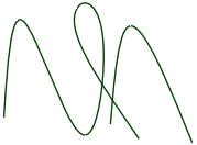
Consolidated multi-segmented curves from a Rhino file
Converter utility
The SpaceClaim Converter is a utility to easily translate between file formats supported by SpaceClaim. It is a separate application, called ‘Converter.exe’, located in the SpaceClaim installation folder.
The Converter is designed to allow you to convert many files from one format to another in a single operation. You can specify files one-by-one and/or choose directories. All files to be converted must be of the same type.
Running the Converter
The Converter is located in the SpaceClaim installation directory. Simply double-click on converter.exe to open the Converter dialog.
Select the files you want to convert. All the files have to be the same format. Build your list using any combination of the commands below.
- Add Files: Opens a dialog to browse to specific files to convert. All files must have the same format. Specify the format by setting the in the Open dialog.
- Add folder: Opens a dialog to browse to a directory containing files to convert. All files matching the File on the Options page will be added.
- Remove: Removes the currently highlighted file(s).
Once you have the list of files to convert, click the Convert button. As the conversion proceeds, you are given the following feedback.
- The file currently being converted is highlighted in Yellow.
- Files that converted successfully are highlighted in Green.
- Files that could not be converted are highlighted in Red. If any file fails to convert, a copy of the file is written to the Failures directory specified on the Options page.
Skip: Click this button to skip (i.e. do not convert) the current file.
Abort: Click this button to cancel the process.
Pause: Click this button to pause the process. When paused, the button switches to Resume.
You need to specify the output file type as well as some other directories used by the Converter. Frequently used conversion settings can be saved and reused.
When SpaceClaim is started from Converter, there is no longer a check for updates in SpaceClaim when it starts.
The Converter options are described below.
- File : When you specify a directory to convert, it may contain many different file types. Since all input files must be the same type, the File specifies which type to convert.
- Recurse directories: Check this option to include subdirectories.
- TimeOut: This is the maximum time allowed for the conversion. It will be aborted if it exceeds this time limit.
- File Type: This is the output file format. All the input files will be converted to this format. Converted files are written to the same directory as the input file.
- Failures Directory: Any files that fail to convert will be copied to this directory.
- Settings Directory: Converter settings can be saved to an XML file in this folder.
- SpaceClaim directory: This is the directory where SpaceClaim.exe is located. Normally this will be the same directory containing Converter.exe.
- Output directory: The converted files will be saved to this directory.
- Email Recipient(s): The converter will send an email to the specified email addresses. You can select when you want email sent with the following checkboxes.
- Abort if failures exceed: Check this box and enter a percentage of failures. The process aborts when the percentage is exceeded.
- Start separate SpaceClaim for each design: A separate SpaceClaim instance is started for each design to avoid memory exhaustion on large models. This sacrifices speed to save memory. The option is Off by default.
- Multiprocess: Multiprocessor support allows multiple SpaceClaim sessions to run in parallel to translate files. This setting is defaulted to the number of cores available, based on your system and available memory, but you can configure it. Be careful not to exceed the number of cores present, and to expect performance of other running programs to degrade potentially.
There is a command line switch (for SpaceClaim) to check for add-ins
- CommandLineAddInsOnly will only load add-ins specified in the command line for SpaceClaim
- For example: /CommandLineAddInsOnly=true
- The switch is primarily intended for use with the Converter to limit the add-ins loaded
- The switch can be used to start SpaceClaim without looking for add-ins in the usual locations
© Copyright 2020 Allied Electronics, Inc. All rights reserved.
 IDs for edges, faces, and bodies are now stored within the .rsdoc file. Object
 ECAD IDF, IDB, EMN