
| SpaceClaim Online Help |
|
The tools in the Sketch group on the Sheet Metal tab are a little different from normal sketch tools:
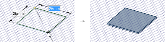
Rectangles, circles, polygons, and ellipses are automatically extruded to the thickness of a sheet metal wall as you sketch. See Sheet metal options to change the default wall thickness. Lines, splines, and arcs are extruded when they form a closed profile.
Sketching in empty space creates new walls.
A preview is displayed as you sketch that shows you the wall thickness for each sketch curve:
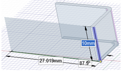
Sketching perpendicular to an existing wall creates a new wall with a bend between the walls with corner or rip reliefs where needed. The bend radius is created inside when the sketch is connected to the top edge and outside when the sketch is connected to the bottom edge:

Sketching on an existing wall creates sketch curves on the wall that you can use with the Bend and Split tools.
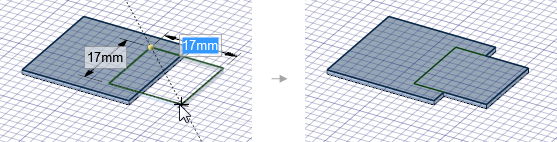
Sketching adjacent to or overlapping an existing wall adds material to the wall and may imprint the overlapping curves on the wall:
In addition, you can choose the Profile option to create a wall that is perpendicular to the sketch plane as you sketch:
The following Sheet Metal sketch options allow you to choose between sketching a flat wall or a wall that is perpendicular to the sketch plane:
|
|
When sketching an open profile (series of lines), a perpendicular wall is created. When sketching a closed profile (square, circle, etc.), a flat wall is created. |
|
|
Any closed sketch creates a flat wall. |
|
When sketching an open profile (series of lines), a perpendicular wall is created. |
|
|
|
Use the starting location of the sketch to determine whether the inside or the outside of the sheet is maintained when bending. |
|
|
Maintains the length of the sheet's inside surface when bending. |
|
|
Maintains the length of the sheet's outside surface when bending. |
The following options are available for every sketch tool:
Cartesian dimensions: Select a point in a sketch and then click this option to see Cartesian dimensions from the point. Cartesian dimensions show you the X and Y distances from the point you select. If you don't have a point selected, it shows you the X and Y distances from the origin.
Polar dimensions: Select a point in a sketch and then click this option to see Polar dimensions from the point. Polar dimensions show you an angle and a distance from the point you select. If you don't have a point selected, it shows you the angle and distance from the origin.
Snap to grid: Select this option turn snapping on or off while sketching. The cursor will snap to the minor grid spacing increment while you sketch. The defaults are 1mm for Metric and 0.125in for Imperial units. See Units options to change the minor grid spacing.
Snap to angle: Select this option to turn angle snapping on or off while sketching. The cursor will snap to the angular snap increment while you sketch. The default is 15 degrees. See Snap options to change the angular increment used for snapping.
Create layout curves: The sketch curves are created as layout curves. If you move the design to a drawing sheet, with Sketch mode selected you must select the Create layout curves checkbox again in the Sketch Options group of the Options panel in order to create layout curves on the drawing sheet. See Layout Curves.
Curve Fitter Options: If the Sketch plane passes through a Mesh object, the system will fit curves through the facet points. Lines are displayed green and arcs are displayed blue. The following options apply to the system-generated curves.
Fit curves - Uncheck this option if you do not want the system to fit curves through the points.
Tolerance - Determines how many points will be found, which also determines how many curves will be created. The smaller the tolerance, the more points will be found and the curves will be generated.
Auto-merge - When checked On, the system will merge linesd and arcs to form splines. Splines are displayed pink.
© Copyright 2014 SpaceClaim Corporation. All rights reserved.
 Auto
Auto Flat
Flat
 Automatic
 Inside
 Outside