
| SpaceClaim Online Help |
|
This tool creates a surface midway between two offset faces. The midsurface faces are automatically extended or trimmed to adjacent faces, and the distance between the faces is stored as a thickness property. You can use these surfaces for FE analysis.
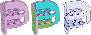
Color highlighting shows you face pairs that have been selected, as shown below. The midsurface face will be offset from the cyan faces. Green indicates that a face is paired with a cyan face. Unselected faces and faces without offsets are shown in the original color.
The thickness of the original model face offsets are stored as a property named Thickness in the Midsurface section of the Properties panel . This is a face property, so you must select the face in the Design window rather than in the Structure tree, even if it is a single face. You can change this property, and it is included in the ANSYS data when it is sent out to ANSYS via the SpaceClaim add-in.
The Midsurface tool detects and removes small faces of midsurfaces that are created when an edge is equal to half of the part thickness.
If the Midsurface tool finds missing faces because neither side can be offset, you will receive an error message in the error box that lists the faces. If the tool fails to create midsurface parts, the problem faces or edges are highlighted.
Midsurfaces inherit the material properties of their parent components, but you can change the material properties for the midsurface object.
Click ![]() Midsurface in the Analysis group of the Prepare tab.
Midsurface in the Analysis group of the Prepare tab.
Select the Use selected faces option in the Options panel.
This option automatically detects all offset face pairs on a body with one or more offset distances.
Click on a face for which you want to create a midsurface.
Click on a second face that makes an offset pair with the first face. All face pairs that have the same offset distance will be added to the selection.
Click detected face pairs to remove them or click undetected face pairs to add them.
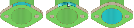
Two faces may be detected as a pair because they have the same offset distance as the face pairs to be midsurfaced. Click on the blue face to remove the pair from selection.
A face pair that should be midsurfaced may not be detected because its offset pair is not a perfect offset of the first face. Click on the face you want offset to add it to the selection. Its midsurface will be offset using the thickness of neighboring detected face pairs.
(Optional) Click the Select Faces tool guide or hold the Ctrl key and select additional face pairs with a different offset distance.
When you add face pairs, all face pairs with the same offset distance will be added to the selection.
Click the Complete tool guide when you are finished selecting faces.
When you successfully create a midsurface, the solid will become semi-transparent and the surface will be opaque until you select a different tool or clear your selection.
Midsurface bodies are created in a component in the Structure tree, and are named using the name of the original object and appended with MidsurfaceN, where N is a unique number.
Midsurfaces are shown in the Structure Tree with a default name that includes the assigned thickness. When you rename the surface, the thickness is appended to the new name.
Click ![]() Midsurface in the Define group on the Prepare tab.
Midsurface in the Define group on the Prepare tab.
Select Use range in the Options panel.
The face pairs with offset distances within the range are automatically detected. If you have face pairs selected, the range will automatically change to include the offset distance.
Click the body for which you want to detect offset face pairs.
Change the Minimum thickness and Maximum thickness values in the Options panel as needed.
Face pairs within this range will be selected; face pairs outside this range will be removed from the selection.
Click the Complete tool guide when you are finished selecting faces.
To add or remove a detected face pair, click either face in the pair.
The midsurface distance will be offset from this face the same distance as adjacent faces, regardless of any potential offset pair for this face.
If the face has an offset pair that was previously selected, the pair will be deselected.
You may need to remove a face from selection if it is paired incorrectly.
Select the midsurface face in the Design window.
Change the Thickness property in the Properties panel.
You can remove the Midsurface association by setting the Thickness to 0.
Select the surface in the Structure tree.
Change the Thickness property in the Properties panel.
The following tool guides help step you through the process. Use the Tab key to cycle through them. As soon as the tool guide switches, the cursor may change to reflect the active guide.
|
|
The Select Faces tool guide is active by default. This tool guide allows you to select a pair of offset faces, and all other face pairs with the same offset distance are automatically detected. |
|
|
The Add/Remove Faces tool guide allows you to select additional faces to offset or remove detected face pairs from the selection. |
|
|
The Swap Sides tool guide allows you to switch the face pairs. You may need to do this when you detect pairs with more than one offset distance, and the offset relationships are incorrectly detected. |
|
|
The Complete tool guide creates the midsurface faces. |
The following options are available in the Options panel:
|
Use selected faces |
Select this option to create midsurfaces for only the faces you select. |
|
Use range |
Select this option to create midsurfaces on all faces in the specified thickness range. |
|
Thickness tolerance |
Change the value of this option to detect offset spline faces with an offset value within the tolerance amount. |
|
Create midsurfaces in |
Select Same component to create the midsurfaces in the same component as the part you selected for midsurfacing. Select Active component to create the midsurfaces in the active component. |
|
Group midsurfaces |
Select this option to create midsurfaces in a new sub-component. Deselect the option to create the midsurface objects in the component you select in the option above (same component or active component). |
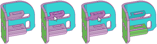
Selecting an additional face pair with the Use selected faces option and the Select Faces tool guide. All face pairs with the same offset are added to the selection.
Removing a face that was automatically detected but not desired as a midsurface pair.
© Copyright 2016 SpaceClaim Corporation. All rights reserved.


