
| SpaceClaim Online Help |
|
Use Section mode to edit solids by working with their edges and vertices in cross-section. You can modify faces, edges, planes, cylinders, rounds, and chamfers in section mode. You can edit solids and surface bodies.
In Section mode, lines represent faces and points (or vertices) represent edges.
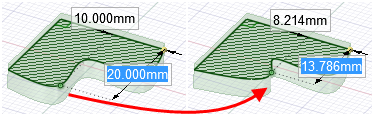
For example, to rotate a face around an edge, select the line that represents the face, Alt+click the vertex that represents the edge, and pull. Moving a sketched line in Section mode does not move the solid it is sketched on. You must move a section line (a line that represents a face) to modify a solid in Section mode.
Hatching is used to show the intersection of the cross-section plane and a solid. Arc centers are shown as small cross marks. Hatching appears bolder inside faces to indicate what is shown in a cross-section view. (See Examples, below).
You can use the following tools: Select, Pull, Move, Combine, Split Body, Shell, Offset, Fill, and all sketch tools. Use the Select tool to edit spline faces (represented by a spline in cross-section). You can also cut, copy, and paste. We recommend that you clip the scene above the grid to enhance the visibility of the cross-section.
Select or de-select options based on whether you want to maintain and view relationships while you edit in cross-section.
Select the face you want to use to create the cross-section plane, or select any faces, edges, or vertices that define a plane.
If you are in a drawing sheet with cross-section views, you do not have to choose a face, as the plane of the drawing sheet is automatically used as the section plane.
(Optional) Move or rotate the cross-section grid and click the Section tool when you are finished.
Click and drag the edges and vertices of the cross-section to edit them.
You can also bend edges with the Bend tool, and pull section points (edges) and section lines (faces) with the Pull tool. If you set the Auto-extrude/revolve sketches in Section modeAdvanced SpaceClaim option, sketch made with the sketch tools are automatically extruded or revolved to form surfaces and solids when you begin the sketch on the edge of an existing surface or solid. To automatically revolve, the sketch must be attached to a revolved face. If you do not begin the sketch on an existing edge, you are switched to Sketch mode.
We recommend zooming into your design so that it is easier to select the correct entity. For example, if you are trying to select an edge, but your design appears very small in the Design window, it is possible to accidentally select a midpoint or end point of the edge instead. Moving the midpoint or end point of an edge will not be reflected by a mirrored entity.
The following options are available in the Section tool:
|
Maintain Mirror |
Select this option to maintain the influence of mirrors in your design while editing. |
|
Maintain Offset |
Select this option to maintain the influence of baselines in your design while editing. Baseline faces |
|
Curve |
If the section plane passes through a Mesh object |
|
|
|
Moving a spline point in section mode
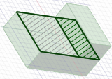
Bold hatching indicates the hatching that would be shown on a drawing sheet cross-section view
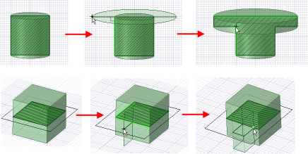
Extruding while sketching in Section mode
© Copyright 2016 SpaceClaim Corporation. All rights reserved.