
| SpaceClaim Online Help |
|
The Spot Weld tool creates points on two faces that represent weld points. Each spot weld consists of two points: one on each face that is to be welded together. Each point must lie on a face or edge. For export to ANSYS, each point must lie on a different solid or surface part.
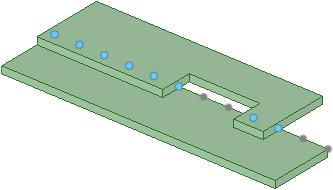
When spot weld points are found on another body, the set does not include points with mates within the same body, as shown below. Weld points in a set that have mates are blue and points that do not have mates are gray.
Spot welds are updated with changes to the guiding edges or base faces.
If a guiding edge disappears, the points created along it are removed.
If a mate face moves out of the search range the weld point, the pairs to that mate face will disappear.
If the mate face moves back into the range, the point pairs will reappear.
If pairs cannot be found for all of the points on the base face, the spot weld is marked in the Structure tree with an error icon showing that it is no longer valid.
Dimensions for spot weld point patterns are displayed in the Design window. These dimensions look the same as dimensions for other patterns.
Spot welds defined for the design can be exported to ANSYS. ANSYS Design Modeler and ANSYS Workbench recognize the weld points with the following limitations:
Only points with mates can be used for simulation.
You may place weld points between multi-body parts if the two bodies belong to different parts. Spot welds defined between bodies in the same part are not transferred to simulation.
You can approximate seam welds by placing weld points on the guiding edge with an offset of zero, if no mating face is found on either side of the base face.
SpaceClaim supports spot welds of more than two weld points (more than two components are welded together at one location), but Simulation does not; Simulation ignores any weld points after the first two supplied.
If a spot weld joint in SpaceClaim contains a spot weld with more than two weld points, then a chain of pairs of weld points is transferred to Simulation as separate spot welds, and each two-point spot weld is listed separately under the Connections node. For example, if a single SpaceClaim spot weld connects parts A-B-C-D, this is transferred as three separate spots welds: A-B, B-C, and C-D.
Click ![]() Spot Weld in the Analysis group of the Prepare tab.
Spot Weld in the Analysis group of the Prepare tab.
Select base face.
This is the face or faces on which the weld points will be defined. You should select a single face or a chain of tangent faces.
Click the Select guiding edges tool guide and select an edge.
This is the edge along which the weld points will be defined. The tool searches for mating edges in the following directions:
The surface normal.
The opposite direction of the surface normal.
If no match is found for a or b, then the direction perpendicular to both the surface normal and edge tangent is searched.
You can hold Ctrl and double-click to select a chain of edges.
(Optional) If you want to define a different mating face, click the Select mating faces tool guide and select a mating face.
You can select more than one face. Clicking on a mating face removes all previously selected faces and holding Ctrl adds a face.
Set the following options:
Start offset: The distance of weld points from the beginning of the guiding edge.
Edge offset: The distance of weld points from the guiding edge.
End offset: The distance of weld points from the end of the guiding edge.
Number of points: The number of weld points to define for each edge chain.
Increment: The distance between weld points.
You can set either the number of points or the increment. The last value you enter will be used. For example, if you change the number of points, the increment will automatically update. If you then change the increment, the number of points will change.
Search range: The distance to search for mating faces from the guiding edge.
Click the Create spot weld tool guide to define the spot welds.
Right-click a face with spot welds.
Select Redetect Mating Faces.
Spot welds will be placed on any new nearby faces.
The following tool guides help step you through the process. Use the Tab key to cycle through them. As soon as the tool guide switches, the cursor may change to reflect the active guide.
|
|
Use the Select Base Faces tool guide to select the face or faces on which the weld points will be defined. You should select a single face or a chain of tangent faces. |
|
|
Use the Select Guiding Edges tool guide to define the edge along which the weld points will be defined. |
|
|
Use the Select Mating Faces tool guide to change the mating face from the face that is automatically detected. You can select more than one face. Clicking on a mating face removes all previously selected faces and holding Ctrl adds a face. |
|
|
The Complete tool guide completes the spot weld definition. |
The following options are available in the Options panel:
|
Start offset |
The distance of weld points from the beginning of the guiding edge. |
|
Edge offset |
The distance of weld points from the guiding edge. |
|
End offset |
The distance of weld points from the end of the guiding edge. |
|
Number of points |
The number of weld points to define for each edge chain. |
|
Increment |
The distance between weld points. You can set either the number of points or the increment. The last value you enter will be used. For example, if you change the number of points, the increment will automatically update. If you then change the increment, the number of points will change. |
|
Search range |
The distance to search for mating faces from the guiding edge. |
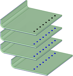
Spot welds that cross over multiple nearby welded parts
© Copyright 2016 SpaceClaim Corporation. All rights reserved.


