| SpaceClaim Online Help |
|
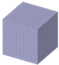
Use the Shell tool to add thickness on the inside or outside of a faceted body.

The following tool guides help step you through the process. Use the Tab key to cycle through them. As soon as the tool guide switches, the cursor may change to reflect the active guide.
|
|
The Select Solid or Faceted Body |
|
|
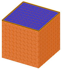
The Select Geometry tool guide allows you to select geometry or facets to be removed when shelling. |
|
|
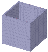
The Complete tool guide completes the shell. |
The following options are available to control how bodies are shelled:
|
Inside |
|
| Outside |
|
| Thickness | Enter a value for the shell thickness in model units. |
| Keep original bodies | Create a new shelled faceted body and retain the original body. |
| Infill Type | Choose the type of infill structure to be created for adding strength to the shelled body when it is 3D printed. |
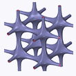
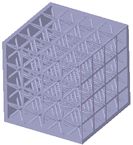
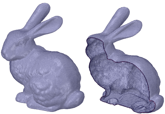
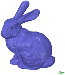
Printing the bunny model above could take a long time and a lot of material, if the entire volume is filled.
Infill lets you shell the interior of a model and add an internal support structure. This provides strength while reducing material costs and printing time.
The tool has several options for controlling the size, shape and percentage of the volume filled.
The following tool guides help step you through the process. Use the Tab key to cycle through them. As soon as the tool guide switches, the cursor may change to reflect the active guide.
|
|
The Select Solid or Faceted Body tool guide is active by default. It allows you to select solid or faceted bodies to shell. |
|
|
The Select Geometry tool guide allows you to select geometry or facets to be removed when shelling. |
|
|
The Complete tool guide completes the shell. |
When you set the Infill Type to be Basic, the following options are available to control the infill:
| Shape |
|
| Sizing Options | The sizing options are linked. Changing one will adjust the others. |
|
Percentage of the shell volume filled by material |
|
Determines the size of the basic shapes used in the infill pattern |
|
Sets the infill wall thickness |
| Preview Options | Allow you to control how the preview is displayed and positioned |
|
Choose the X, Y, Z axis, or the Screen to set the preview direction. |
| Use the dropdown slider to drag the preview along its normal direction. Use the Reset button to go back to the previous location. |
Set the Thicken direction to Inside
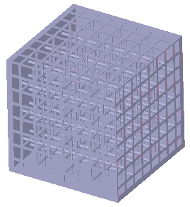
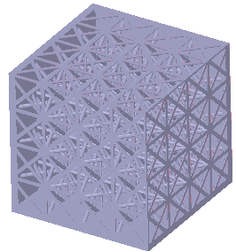
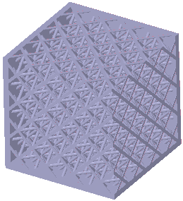
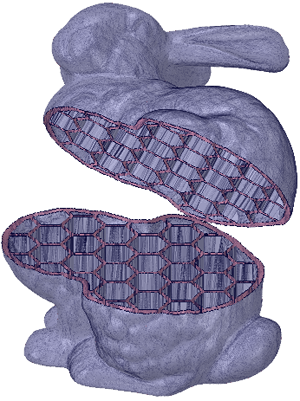
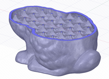
The images below show preview for Square and Hex Infill shapes.
The Y-axis is chosen for the preview Direction and the Offset was adjusted to place the preview near the middle of the model along the Y-axis.
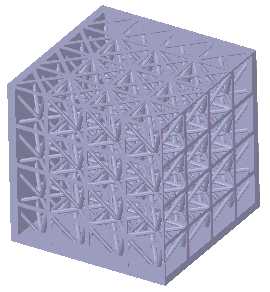
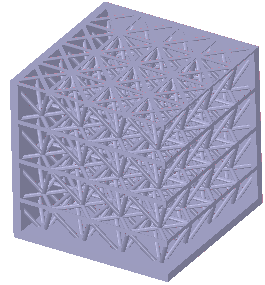
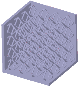
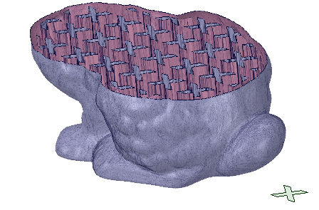
The image below shows the model shelled with a Hex infill. The body was split and moved to expose the Infill.
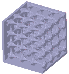
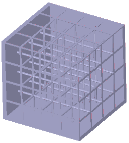
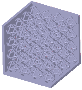
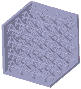
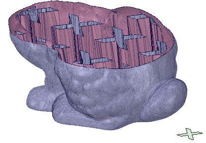
The image below shows the model shelled with a 3D lattice infill.

|
Lattice infills are sensitive to the coarseness of the faceting. Coarse facets produce lattice infills faster. Coarseness is controlled when you convert a solid body to a faceted body using the Convert tool. When converting, use a Maximum Angle in the neighborhood of 30° to get fewer facets and speed up the lattice calculations. |
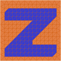
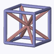
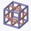
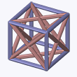
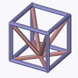
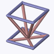
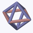
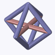
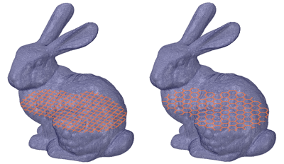
You can also use Custom shapes for the Infill. In the example below, the "X" shape will be used as a Custom Infill.
The following tool guides help step you through the process. Use the Tab key to cycle through them. As soon as the tool guide switches, the cursor may change to reflect the active guide.
|
|
The Select Solid or Faceted Body tool guide is active by default. It allows you to select solid or faceted bodies to shell. |
|
|
The Select Geometry tool guide allows you to select geometry or facets to be removed when shelling. |

|
The Select Sketch tool guide allows you to select a sketch to be used as the custom infill shape. |
|
|
The Complete tool guide completes the shell. |
When you set the Infill Type to be Custom, the following options are available to control the infill:
| Pattern |
pattern or Rectangular Grid pattern |
| Sizing Options | |
|
When you choose this option, you enter a length for scaling the selected custom infill shape. This allows you to increase or decrease the size of the custom shape. The option is Off by default, which uses the custom shape as-is. |
|
Sets the infill wall thickness |
| Fill Options | |
|
The selected shape will be filled with material leaving voids between the shapes. |
|
The space between the shapes will be filled leaving a void in the interior of the selected shape. |
Set the Thicken direction to Inside
The images below show some examples.
|
The "X" shape in the lower left corner is chosen as the custom infill. Scaled to fit is used with a larger dimension to create a larger space between shapes. Fill Shape was chosen to fill the custom shape and leave a void between shapes. |
|
|
The "X" shape in the lower left corner is chosen as the custom infill. Scaled to fit is NOT used so the shape is applied as-is, which creates and a smaller space between shapes. Fill Shape was chosen to fill the custom shape and leave a void between shapes. |
|
© Copyright 2017 SpaceClaim Corporation. All rights reserved.


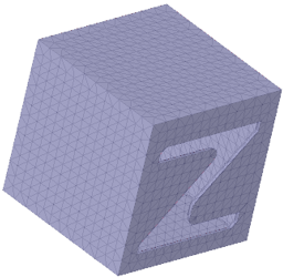
 Example using the Select Geometry tool guide.