


Creating a Pattern
Creating a One- or Two-Dimension Linear Pattern
- Click the
 Linear tool in the Insert
group on the Design tab.
Linear tool in the Insert
group on the Design tab. Select a protrusion, depression, body, sketch, points, axes, planes, origins, or 3D curves to be the first member (leader) of the pattern. The Direction tool guide activates.
Select a line, edge, axis, or a set of points to set the direction of the pattern.
(Optional) Modify the Pattern options in the Options panel.
Pattern Type: One-dimensional or Two-dimensional.
Change X Count, or X Pitch values for One-dimensional
Change X, Y Count, or X, Y Pitch values for Two-dimensional
As you switch between pattern types, or change pattern values, the pattern preview displays your changes in blue.
- Select the Create Pattern tool guide, or press Enter, to complete the pattern.
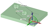
The image below shows the preview for a two-dimensional pattern. For one-dimensional, only the X-direction is displayed. Clicking the arrows flips their direction 180-degrees.
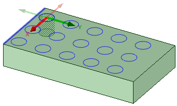
For through-all cuts, the preview is on the plane closest to the direction reference. For blind cuts, the preview is on the face of the selected pattern leader.
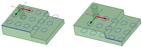
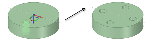
You can also create one-dimensional linear patterns on cylindrical faces as long as the pattern direction is either the cylinders axis or parallel to the axis.
Creating a Pattern of a Pattern
Follow the steps for the linear pattern, but select a member of a linear pattern as the first member of the pattern.
Creating a Circular Pattern
- Click the
 Circular tool in the Insert
group on the Design tab.
Circular tool in the Insert
group on the Design tab. Select a protrusion, depression, body, sketch, points, axes, planes, origins, or 3D curves to be the first member (leader) of the pattern. The Direction tool guide activates.
Select a line, edge, axis, or a set of points to set the direction of the pattern.
(Optional) Modify the Pattern options in the Options panel.
Pattern Type: One-dimensional or Two-dimensional.
Change Circular Count, or Angle values for One-dimensional.
Change Circular Count, Angle, Linear Count, or Linear Pitch values for Two-dimensional.
Note that a Circular Count of one will create a single radial pattern.
As you switch between pattern types, or change pattern values, the pattern preview displays your changes in blue.
Select the Create Pattern tool guide, or press Enter, to complete the pattern.
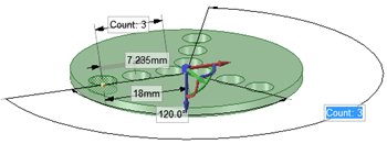
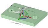
The image below shows the preview for a two-dimensional pattern. For one-dimensional, only the Angular direction is displayed. Clicking the arrows flips their direction 180-degrees.
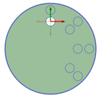
You can create circular patterns on cylindrical faces, both around the face and along the axis.
Creating a Fill Pattern
- Click the
 Fill tool in the Insert group
on the Design tab.
Fill tool in the Insert group
on the Design tab. Select a protrusion, depression, sketch, points, axes, planes, origins, or 3D curves to be the first member (leader) of the pattern. The Direction tool guide activates.
Select a line, edge, axis, or a set of points to set the direction of the pattern.
Modify the options in the Options panel
Pattern Type: Grid or Offset
Modify the X Spacing or Y Spacing
Modify the Margin values. A dashed orange boundary line displays the pattern's marginal boundary.
As you switch between pattern types, or change pattern values, the pattern preview displays your changes in blue.
Select the Create Pattern tool guide, or press Enter, to complete the pattern.
Creating a Radial Circular Pattern
Select all radial pattern members.
Click the
 Move tool.
Re-anchor the Move tool on the circular axis.
Select the Create patterns check box in the Options panel.
Drag the radial pattern to form a circular pattern.
Create a Pattern of Points Along an Edge
Select a point to be the first member of the pattern.
Click the
Move tool.Select the Create patterns check box in the Options panel.
Click the Move Along Trajectory tool guide.
Click one of the edges that connects to the vertex.
Click the Move handle axis.
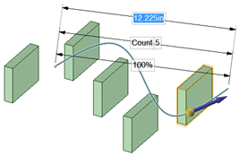
Drag to create the end pattern member and create the pattern.
Press Tab to change the count, length, and percent fields to edit the pattern of points.
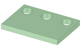
All points are associated with the edge, so that when the edge changes, the points also change as shown in the example below.
Editing a Pattern's Properties
Select one pattern member to display the pattern count and dimensions.
Edit the pattern's properties.
Press Tab to switch between the fields.
Click the lock icon to lock or unlock a value.
Note: By default, Pattern Length is locked.Press Enter.
The result of editing the count and spacing is relative to the member of the pattern you select.
Moving a Pattern
Click the
Move tool.Select a pattern member to move a linear pattern or the pattern axis to move a circular or arc pattern.
Move the pattern member with the Move handle.
If you move an interior member of a pattern and it is not anchored, all the pattern members move:
If you move a member at one end of a pattern, the member at the opposite end is anchored and the pattern is skewed:
If you anchor a different member than the member opposite the direction you are moving, Move skews the pattern.
If you have a linear pattern in a radial direction and you move an interior member without setting an anchor, then the entire pattern shifts in the selected direction
Use the Up To tool guide to move a pattern member up to another face or edge. Pattern dimensions (such as Count and Length) display as expected.
You can also use the Up To tool guide in the Move tool to create a circular pattern by rotating up to a linear entity passing through the Move Handle origin.
Creating a Circular Pattern Using the Up To Tool
- Relocate the Move handle to the axis of the cylinder.
- Choose the rotation handle about the cylinder's axis.
- Click Up To and select the horizontal axis to create the pattern.
Moving a Radial Pattern in a Linear Direction
Click the
Move tool.Right-click a pattern member and click .
Select the Direction tool guide.
Click an object to set the direction of the move.
Drag the pattern.
Adjusting Pattern Distance or Spacing
Click
 Select or
Move in the Edit group on
the Design tab.
Select or
Move in the Edit group on
the Design tab.Select a pattern member.
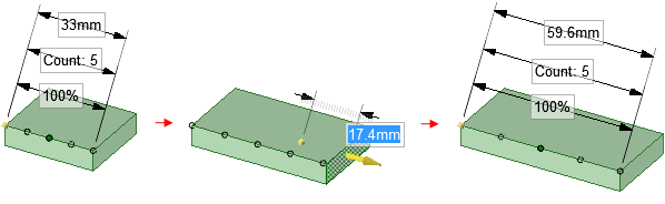
This member will serve as the anchor, and other pattern members will move relative to this member.
Press Tab until the field you want to change is highlighted:
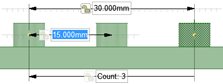
Distance: This field is the overall distance of the pattern. The pattern member you select is anchored, and the length will change relative to this member. The arrows indicate the direction of change. You can see this field at the top of the image below.
Spacing: This field is the spacing between pattern members. This field has arrows in both directions and is located between two pattern members. The field is highlighted in blue in the image below.
Radial patterns: If you select a member of a radial pattern, you can change the angle between pattern members and the distance from the pattern members to the center of the pattern.
Type a new distance or angle and press Enter.
The spacing between all pattern members will change.
Removing a Pattern Member from the Pattern
Right-click the face of the pattern member and select Unpattern Member. Doing this makes the member independent, so changes to the feature won't propagate to the pattern.
Creating a Pattern Group
Select a pattern or pattern member in the Design window.
Click the Groups tab in the Structure panel.
Click Create NS.
A group is created that displays the number of members in the pattern. You can click this group to select the pattern and change its parameters in the Design window.
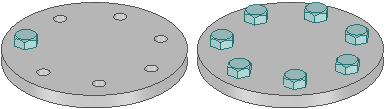
Assembling Components on a Pattern
You can assemble a component with a pattern member, then propagate the component to all of the pattern members. The component will be copied and assembled to each pattern member.
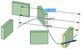
Creating a Pattern Along a Trajectory
Click
Move tool.Select the object you want to pattern.
Click the Move Along Trajectory tool guide and select the curve to use as a trajectory.
You can also hold Alt and double-click the curve.
- Check Create Patterns in the Move options.
- Pull the trajectory arrow.
- Release the mouse button to display pattern dimensioning options, then enter values by tabbing through the options.
- (Optional) Check Maintain Orientation in the Move options to keep the patterned objects in the same orientation as the original object.
Pattern along a trajectory without maintaining orientation.
Pattern along a trajectory with orientation maintained.