Converting an Existing View to a Cross-Section View
Click the Cross Section View tool on the Detailing tab's Views ribbon group.
Click the Select Section View tool guide and select the view
you want to convert to a cross-section.
If dotted gray lines
do not appear around the view, it is not selected. If this occurs,
press Esc and try again.
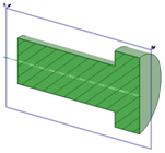
Set the Create a Total Cross-Section option to set the view's
section type property to Total. Uncheck the option to set the
property to Area. See examples in the image above.
Mouse over a related view to display the cross-section indicator and
preview the cross-section.
The indicator line snaps to
geometry in the view. Geometry in front of the cutting plane is not
displayed.
Click to place the cross-section indicator and create the
cross-section view.
The view is labeled
automatically.
Press Esc or S to exit the tool.
Modifying a Cross-Section View
Move the cross-section indicator to change the cutting
plane.
Select the cross-section view.
Modify the values in the Properties panel, or right-click and select
a style from the mini-toolbar. Change the value in:
Orientation Type to change the cross-section view to
a General view. This makes the selected view independent of
the view used to create it.
Rendering mode to change the graphics style for the
view. Select Inherit if you want to link the graphics
style to the parent view.
Scale to magnify or shrink the view. When you change
the scale, the Type property changes to Independent from
sheet. You can select Linked to sheet to set
the scale to be the same as the scale used for the drawing
sheet.
Section Type to create a total or area cross-section.
Select Total to display 3D geometry not on the cross
section plane. Select Area to display only the
geometry on the cross-section plane. You can select
None to turn the view into a General
view.
Select a region within the cross-section view.
Modify the values in the Properties panel. Change the value in the
following Cross hatching properties:
Exclude from sectioning to remove the selected region
from the cross-section view.
Fill styles to add or removing hatching from the
region.
Angle to modify the angle at which the hatching lines
are drawn.
Spacing to modify the space between hatching
lines.
Offset to modify the start point of the first
hatching line.
Reversing the Direction of a Cross-Section View
Right-click the cross-section arrow and select Flip Viewing
Direction.
Publishing a Cross-Section View to 3D
Right-click the cross-section view on the drawing sheet or in the
Structure tree.
Select Publish to 3D from the context menu.
A published
section appears as a root node in the Structure tree.
You can
right-click the published cross-section in a Design window and
select Clip with Plane. You can also use the Move tool to
move a published cross-section.
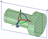
Examples
Selecting a published cross-section to clip with plane.
Using the Move tool to move a published cross-section.