


Creating a New Drawing Sheet
Select New > New Drawing Sheet from the File menu.
A drawing sheet containing top, front, and right-side views appears in the Design window, and the Drawing Sheet appears in the Structure tree. The Detailing tab is displayed. You do not need to create a design before creating a drawing sheet. DesignSpark Mechanical allows you to create and edit geometry within the drawing sheet itself. When you create a new drawing sheet for an empty design, the sheet contains the view outlines, with handles you can use to control the size and position of the view. You can delete the handles and move the view using the outline.
If you began a design from an empty drawing sheet, you can right-click a design on the drawing sheet and select Open Component to display the design in a new Design window.
Modifying one view changes the related views as appropriate.
Displaying a Drawing Sheet in the Design Window
Right-click the sheet in the Structure tree and select Open Sheet from the context menu.
Deleting a Drawing Sheet
Right-click the sheet in the Structure tree and select Delete from the context menu.
The drawing sheet window closes. If the drawing sheet is no longer referenced by any other open design document, it is removed from active memory. It is not deleted from other documents that reference the drawing sheet.
Changing the Visual Orientation of a Drawing Sheet
You can orient a drawing sheet using the normal mouse + keyboard combinations and menu commands. For example, you can press the middle mouse button and drag to spin the drawing sheet. See Orienting.
Right-click anywhere in the drawing sheet and select View > Flat View from the context menu to view the sheet head-on.
Drawing sheets have separate named views in the Views tab. These are the views used to orient your sheet in the design area. The default named views are
Home: Changes the view to head-on by default. Can be set to a different view.
Plan View: Changes the view to head-on based on the face you have selected. If nothing is selected, the sheet is oriented to the drawing window.
Flat View: Changes the view to head-on for the drawing sheet.
See Customizing views.
Editing Design Annotations
Right-click the annotation plane in the Structure tree and select Show all dimensions to display any design annotations on that plane. Click an annotation to edit it. Changes made on the drawing sheet will also appear in the design.
Controlling the Visibility of Objects in a Drawing Sheet
The Structure tree in a drawing displays the design components under each drawing. You can:
- Hide or show a view: Check or clear the box next to the view in the Structure tree. You can also right-click the view in the drawing sheet and select Hide from the context menu.
- Hide or show a component in all views: Right-click the component in the Structure tree and select Hide in all views or Show in all views from the context menu.
- Hide or show a component in a particular view: Check or uncheck the box next to the component in the Structure tree.
Hide or show an object in all views: Right-click the object in the Structure tree and select Hide in all views or Show in all views from the context menu.
Hide or show an object in a particular view: Right-click the object in the drawing sheet and select Hide in Selected View from the context menu. Check the box in the Structure tree to restore visibility.
- Isolate a solid in a view: Right-click the solid in the Structure tree and select Isolate in selected view from the context menu. You can also right-click a face of the body in the drawing sheet. All geometry in the view disappears except the selected object. This option is not available for components.
- Hide an individual curve in a component instance: Right-click the curve and select Hide from the context menu. You can also check or clear the box next to the curve in the Structure tree.
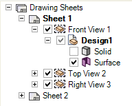
The Structure tree displays a mixed visibility state for any objects hidden in a view, as shown in the figure below.
Visibility in a drawing sheet is independent from the visibility of the model in the design window.
If you insert a model into a new document, the model appears with the visibility saved in the document. After the model is inserted, the visibility of objects is independent of the saved document.
When you create a new view (general view, projected view, cross section, or detailed view) in a drawing sheet from an existing view in your drawing sheet, the visibility of objects is copied to the new view.
Opening a Root Part in the Design Document
Right-click a root node in the Structure panel of a drawing sheet and select Open Root Part.
In a drawing sheet opened from a component-only design document, right-click the component root node and select this option to display the design document for the full assembly. In a drawing sheet without any views, right-click the Drawing Sheets root node and select this option to display the design document for the assembly.
Duplicating a Drawing Sheet
Right-click the sheet in the Structure tree and select Duplicate from the context menu.
The drawing sheet and its views are duplicated in a new drawing sheet.
Copying and Pasting a Drawing Sheet
You can Copy and Paste Drawing Sheets with all Annotations, Formats, Tables, and Content.
- Select a Drawing Sheet in the Structure Tree
- Click Copy in the ribbon, or use the Ctlr+C shortcut
- Click Paste in the ribbon, or use the Ctrl+V shortcut