


Importing: Supported File Types
AMF
V1.0 (Facets)
3D - parts, assemblies
.amf
Import also supports compressed AMF.
You can stop AMF import using the Stop button when image processing takes too long.
Body names and colors are supported.
AutoCAD®
R12 to 14, 2000, 2004, 2007, 2010, 2013, 2016, 2018, 2021, 2023
Includes Polyface Meshes
.dwg, .dxf
AutoCAD drawings can be inserted as layouts.
If you import an AutoCAD file and you don't see the geometry you expect, try changing the import options. See File import and export options.
You can import "Proxy entities" in AutoCAD DXF and DWG files when you select the TeighaDWG option.
If an AutoCAD file does not open, try changing the DWG option to RealDWG.
Layout space entities can be imported using the Teigha option, Sketch curves and text can be imported into Designs, and 2D entities can be inserted to Drawing Formats.
Layout Spaces are imported into separate windows.
Empty Layout Spaces are ignored on import.
Layout Spaces are only supported for Teigha, not RealDWG.
Body Arrays: Geometry created using the AutoCAD "Array" command will not automatically be imported into Ansys Workbench. To import the bodies in the array, do the following:
Load the drawing file into AutoCAD
Select the array
Issue the "Explode" command
glTF
Not supported
IGES
versions up to 5.3
parts, assemblies
.igs, .iges
Curves and Curve Colors are supported on import.
Image Files
files (insert only)
.bmp, .pcx, .gif, .jpg, .png, .tif
OpenVDB
.vdb
Point Curve Text
curves (insert only)
.txt
A spline curve is created by default or if the option
Polyline=Falseis used. If the optionPolyline=Trueis used, then the points are connected by straight line segments.By default, 2D curves are created. When specifying 2D curves, the first column of the data points must be an integer and gives the height of the plane of one of the curves. The beginning of a new curve is specified by changing this height from one line to the next. If option
3D=Trueis used, the curves can be 3DUse the Fit keyword to specify whether Curve Fitting or Interpolation is used.
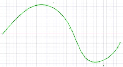
Fit=Trueuses Curve Fitting. Curve Fitting creates a curve that "Fits" the data points using a specified tolerance. The curve may not pass exactly through all points and the distance from the curve to the point will be within the tolerance.Use the
Fittolkeyword whenFit=Trueto specify the Curve Fitting tolerance in model units. For exampleFittol=1.0e-2The curve below uses Curve Fitting (that is, Fit=true). A large tolerance (fittol=2.0) is used to exaggerate the fact that the curve does not pass through the points but only gets within the specified tolerance.
Fit=Falseuses Interpolation. Interpolation requires that the curve pass exactly through all of the points. An interpolation method is used to build a continuous curve through all of the points.The curve below is interpolated (that is,
Fit=False). There are seven points in the file and the curve passes exactly through each one.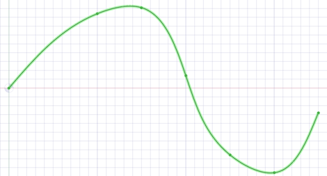
Multiple curves are separated by blank lines.
You can import point curve text files that contain single-point curves, which will be created as points.
Point-curve text files opened or inserted in display a closed curve when the file has a repeated value.
Curves can be imported to coordinate systems or other geometry like other imported objects.
Point-curve text files with columns separated by commas can be opened or inserted. This feature allows you to import any comma-separated value file into .
If there is an error reading the input text file, a message will appear with the line number of the error in parentheses followed by the text appearing on that line.
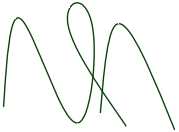
The following example shows the contents of a point curve text file on the left and the 3D curves it creates on the right:
Note that the point coordinates are (Z, X, Y).
For example (1, 2, 3) is (Z=1, X=2, Y=3).
|
3d=true polyline=false 1 0 0 1 0 1 1 1 0 1 1 1 2 0 1 2 1 0 3 0 0 3 0 1 3 1 0 |
 |
Keywords:
-
polyline=false- spline curves are created. -
polyline=true- straight lines are created. -
3d=true- 3D curves are created. -
3d=false- curves are two-dimensional. This is also the case if the option is not set. -
fit=true- use Curve Fitting.- Curve Fitting finds the "Best Fit" through the points.
- Does not require the curve to pass through all of the points
-
fit=false- use Interpolation.- Interpolation forces the curve to pass through all the points in the file.
-
fittol=1.0e-2- Curve Fitting tolerance in the units used in the file.
The blank line after the first set of coordinates indicates that the next set of coordinates is a new curve.
You can copy the file contents above and paste them into a text file, then
use  Insert File to try it yourself.
RS Components
V2015.0 SP0
parts, assemblies
.rsdoc
rsdocs can only be imported for the first 30 days after DesignSpark Mechanical activation. After 30 days, a limit of 100 individual file imports is enforced.
SketchUp®
Up to SketchUp 8, V2013, V2014, V2018, V2019, V2020, V2021
parts, assemblies
.skp
STEP
AP203, AP214, AP242 (geometry)
parts, assemblies
.stp, .step
When you import STEP assemblies from one file, select the Create multiple documents when importing assemblies file option if you want the assemblies to remain in one file instead of being split into multiple files, one for each internal component.
- Origin import and export is supported
- PMI import is supported
- License is required
STL
Facets or Solids
parts, assemblies
.stl
When exporting STL files, the output is set to Binary by default.
When saving as an .STL file, the quality is based your graphics quality setting. You should set the option to enable the highest possible graphics quality if you want your design to be useful as an SLA rapid prototype for form, fit, and function purposes.
You can import an STL file as a solid, if it has multiple planar areas that can be merged into one planar face.
Video files
files (insert only) with proper codec(s) required for all but WMV and AVI
.wmv, .avi, .flv, .mkv, .mov, .mp4, .mpg, mpeg, .ogm, .vob
Wavefront
Facets
parts, assemblies
.obj