


Setting the Mesh Type on a Face
- On the ribbon, click Map/Sweep
 .
. - Click Select face
 .
Note: The Map/Sweep control can be applied to geometry faces or block faces. If the Ghost blocked geometry option is enabled (default) and the mesh has been generated, blocking faces will be selected. To select geometry faces instead, disable the Ghost blocked geometry option or hide the blocking in the Structure tree.
.
Note: The Map/Sweep control can be applied to geometry faces or block faces. If the Ghost blocked geometry option is enabled (default) and the mesh has been generated, blocking faces will be selected. To select geometry faces instead, disable the Ghost blocked geometry option or hide the blocking in the Structure tree. - In the Mapping Options panel, choose a mesh
type.
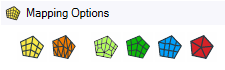
Options are: - Mapped Quadrilateral
 : (Default) Instructs the mesher to create a structured face mesh with
all quads.
: (Default) Instructs the mesher to create a structured face mesh with
all quads. - Mapped Triangles
 :
Instructs the mesher to create a structured face mesh with all
triangles.
:
Instructs the mesher to create a structured face mesh with all
triangles. - Semi-structured
 : Instructs the mesher to create a
semi-structured face mesh with all quads. For more details, see Semi-structured Mesh Type.
: Instructs the mesher to create a
semi-structured face mesh with all quads. For more details, see Semi-structured Mesh Type. - Free Quadrilateral
 :
Instructs the mesher to create a free face mesh with all quads.
:
Instructs the mesher to create a free face mesh with all quads. - Free Quadrilateral Dominant
 : Instructs the mesher to create a free face
mesh with mostly quadrilaterals. You can also choose to use the Prime surface
mesher with this option.
: Instructs the mesher to create a free face
mesh with mostly quadrilaterals. You can also choose to use the Prime surface
mesher with this option. - Free Triangles
 :
Instructs the mesher to create a free face mesh with all triangles. You
can also choose to use the Prime surface mesher with this option.
:
Instructs the mesher to create a free face mesh with all triangles. You
can also choose to use the Prime surface mesher with this option.
- Mapped Quadrilateral
-
If the face is only attached to four edges and four vertices the
mapping is clear. If the face has more than four edges/vertices attached, you need to
define how the software should map/submap the face by marking the vertices
appropriately.
To set the vertex type: Select vertices
 will be
activated.
will be
activated.Click a vertex and select the vertex type (default is end vertex).

Repeat click a vertex and select the vertex type as necessary.
Note: A mapped face requires four End vertices. You can either select the 4 end vertices or, for example, if you have 5 vertices for a given face you can simply mark 1 vertex as a side and the other 4 vertices would be end vertices.For more information, see How Vertex Types Affect the Mapped Mesh. Tip: For the special case of converting an annular face (two concentric loops of edges) from free to mapped, you do not need to specify any side or end vertices. The software is able to recognize the annular face and split it into four mapped faces. On a solid model, the swept block is converted to four mapped blocks when the free, end face is converted to mapped.
- Click Complete
 to set the
mesh type control.
to set the
mesh type control.
The Map/Sweep control can also be used to adjust mesh after it has been created. If using the Map/Sweep control with an already meshed model, use the face control to adjust the block face mesh type. For example, a free face (any mesh type), can be converted to a mapped face (any mesh type), or vice versa, in order to help with converting free blocks to swept blocks or swept blocks to mapped blocks or vice versa.
To convert a block face type, simply select the option you want to convert the block face to, and then pick the face. The block face will be converted accordingly. If in Play mode, the mesh will be updated. If in Pause mode, the mesh will not be updated until you turn on Play mode, however, you can continue converting other face types or solid block types without updating the mesh.

Semi-structured Mesh Type
The semi-structured face mesh type is used to transition mapped mesh along one direction while keeping mapped mesh along the other direction. As such two parallel edges should have the same edge sizing and the other two edges should have a transitional size that is of the form: edge1 = edge2 +/- 2*n where n is the number of transitions. In the example below:
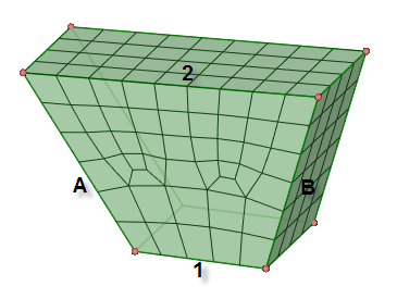
Edge divisions for A and B should be equal and Edge divisions for 2 would be equal to the number of divisions for 1 +2*2 transitions. Edge 1 has 5 divisions and Edge 2 has 9 divisions as there are two transitional regions.
Corners are handled during meshing, as shown in the example:
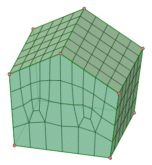
Mesh orientation is also controlled by the sizing specified. For example, here the sizing specifies 10 divisions for the top two edges combined and 10 divisions on the edge at bottom, 5 on left and 3 on right (1 transition)
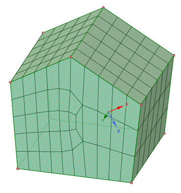
For the same example, specifying 4 divisions on the right edge would result in a mesh as shown:

Adjusting the sizing, for example, 11 divisions on the right edge will result in the mesh converted to semi-structured (5 divisions on the left + 3 transitions * 2 = 11 divisions on the right).
Using Prime Surface Meshing
While creating a free mesh using quadrilateral dominant or triangle mesh type, an additional option is available to enable Prime surface meshing. When the Use Prime option is enabled, an alternative surface meshing method is used for faster surface meshing performance for models having large surfaces with many cut out loops. By default, this option is disabled. Note that the surface mesh quality may deteriorate when this method is used.
How Vertex Types Affect the Mapped Mesh
The vertex type affects the shape of the face mesh in the vicinity of the vertex. A vertex can be end, side, or corner based on the number of face mesh lines that intersect the vertex, and the angle between the edges immediately adjacent to the vertex.
Vertex types are specific to the faces upon which they are set. A vertex can only have a single vertex type for a face. If a vertex is associated with multiple faces, it can possess a different type for each face. For example, a vertex could have a side type with respect to one face, and an end type with respect to another face, as long as two separate mapped mesh controls are defined for the two faces.
The following table describes the different vertex types and how they affect the mapped mesh:
| Vertex Type | Intersecting Mesh Lines | Range of Angles Between Edges | Description |
|---|---|---|---|
| End Vertex |
0 | 0° - 135° |
Select with Creates the mapped mesh such that only two mesh element edges intersect at the vertex. The vertex is attached to one quad element on the mapped face. As a result, the mapped and sub-mapped face mesh patterns on both sides of the End vertex terminate at the edges adjacent to the vertex. Assigning the End vertex type to a vertex whose adjacent edges form an angle greater than 180° will likely result in mesh failure. |
| Side Vertex |
1 |
136° - 179° (faces with only 4 vertices and 4 edges) 136° - 224° (all other faces) |
Select with Creates the mapped mesh such that three mesh element edges intersect at the vertex. The vertex is attached to two quad elements on the mapped face. The two topological edges that are adjacent to the vertex are treated as a single edge for the purposes of meshing. |
| Corner Vertex |
2 | 225° - 314° |
Select with Creates the mapped mesh such that four mesh element edges intersect at the vertex. The vertex is attached to three quad elements on the mapped face. Assigning the Corner vertex type to a vertex whose adjacent edges form an angle less than 180° will create an unnecessarily bad quality mesh (although the mesh will be valid). |
| Reset Vertex type. |
Select with Resets the selected vertex to its default type. |