


Tool Guides
The following tool guides help step you through the process. Use the Tab key to cycle through them. As soon as the tool guide switches, the cursor may change to reflect the active guide.
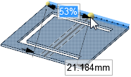
| Select Cutter Point: Click a point on an edge to create a bend that is perpendicular to the edge at the point. Press Tab to enter a value for the percentage or distance from the bend to the endpoint along the edge. |
|
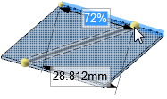
| Select Two Cutter Points: Click a point on one edge and a point on another edge to create a bend between the points. You can see a preview of the line as it extends to the second edge before you click it. Press Tab to enter a value for the percentage or distance from the bend to the endpoint along the edge. |
|
| Select Anchor Point: Select the face you want to remain fixed when the body is bent: |
|
| Select Curves: Select curves to be wrapped around bends. |
|
Adding Bend Steps
- Select a bend.
- Modify the Bend Steps value in the Sheet Metal section of the Properties panel.
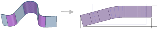
Adding bend steps creates a bumped bend, which instructs the operator and machine to create a large radius bend by bumping instead of "rolling" smoothly. The bend is hit with a sharp tool, creating closely spaced sharp bends that form a large bend.
To display the bend steps and bend dimension properties of the bend in an unfolded sheet metal part, turn on the visibility in the Bends and Bend Dimensions layers in the Layers panel or in the Style ribbon group on the Display tab.
Creating a Joggle
- Click the
 Bend
tool in the Create group on the Sheet Metal tab.
Bend
tool in the Create group on the Sheet Metal tab. - Select the
 Create Joggle option in the Bend Options panel.
 (Optional) Modify the following values in the Bend Options panel:
- Bend angle: the angle for both bends of the joggle
- Bend radius: the inside radius for both bends of the joggle
- Joggle height: the measurement between the top of the sheet going into the bottom bend and the top of the sheet coming out of the top bend.
Bend Allowance: Value to use for calculating the flat length of the joggle.
Bend Deduction: Value to use for calculating the flat length of the joggle.
- Use the Select Cutter Point or Select Two Cutter Points tool guide to create the bottom bend of the joggle.
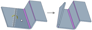
Click to select the second bend of the joggle, which is previewed as you mouse over the sheet metal face, as shown below.
If necessary, you can click an empty space in the Design window to clear your selections and activate the Select Cutter Point tool guide.
Use the Select Anchor Point tool guide to select the face to remain fixed when the rest of the body is bent to create the joggle.
Click the Complete tool guide to create the joggle.
You can move the walls between joggles.
Creating a Joggle from Existing Bends
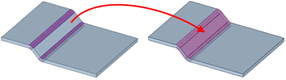
- Select two bends with a face between them.
Right-click and select Create Joggle From Bends from the context menu.
The face between the two bends is added to the joggle. The highlighting color changes to indicate the joggle.
Returning a Joggle to Independent Bends
Right-click the joggle and select Explode Joggle from the context menu.
The independent bends remain selected. If you want to return the bends to a joggle, right-click and select Create Joggle From Bends.
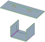
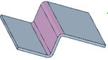
Examples
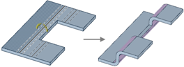

Joggles created using the Bend tool.
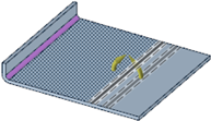
Creating a Bead Using the Bend Tool
- Click the
Bend
tool in the Create group on the Sheet Metal tab.
- Select the
 Create Bead option in the Bend Options panel.
 (Optional) Modify the following values in the Bend Options panel:
- Bead radius: The radius of the bead, which is also the height of the bead. The minimum bead radius is 0.25xT (sheet metal thickness).
- Round radius: Radius of the round at the base of the bead that intersects with the surface.
- Click a curve on the sheet metal face, or select a tool guide and select bend points based on the tool guide you use.
- Click the
 Bend tool guide to complete the bead.
You can also create a bead using the Bead tool.