


Adding a Swept Edge Form to Your Design
- Sketch a profile at an endpoint of the edge.
- Enter the Pull tool.
- Click the Sweep tool guide.
- Click the Full Pull tool guide.
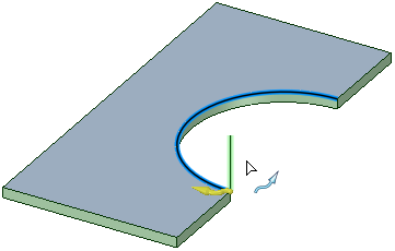
The vertical line will be swept along the arc to create the form.
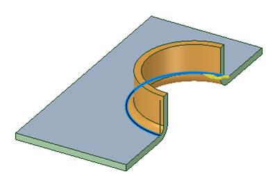
Notice that the sweep profile is a single line and an Inside Radius arc is automatically added to the profile, at the attachment point, to produce a bend. If you draw a tangent arc along with a line, then that arc determines the bend radius and overrides any inside radius automation that is done in the case of only a straight line.
Swept Edge Forms can be unfolded.
Adding a Countersink or Special Form
- Click
 Forms in the Forms group on the Sheet Metal tab.
 - Hover over the illustration thumbnail in the Options panel to see a larger illustration with each dimension or value.
Click to select a form from the Countersink or Special gallery.
- The Options panel updates to display specific parameters for the form type you selected. These parameters will be saved as properties for the form.
Select the face to use as the form shape.
- Click the Complete tool guide to create the form or double-click to select the face and complete the form in one step.
Adding a User-defined Punch, Knockout, Extrusion, or Cup Form
- Click
Forms in the Forms group on the Sheet Metal tab.
Select a user-defined form in the punch, knockout, extrusion, or cup sections of the gallery that opens below the tool icon.
If you are adding an extrusion or cup form, you can change the form parameters in the Options panel.
Hover over the illustration thumbnail in the Options panel to see a larger illustration with each dimension or value.
These parameters will be saved as properties for the form.
Select the face to use as the form shape.
- Click the Complete tool guide to create the form or double-click to select the face and complete the form in one step.
Adding a Custom Embossed Form to Your Design
Click
Forms in the Forms group on the Sheet Metal tab.Click Emboss in the Custom Tools section at the bottom of the gallery.
Click the arrow at the bottom of the gallery to scroll down if you don't see the Custom Tools section.
Set the following parameters in the Options panel:
Distance: The distance that the section of wall will be offset.
Round radius: All edges that are created are automatically rounded to this radius. Set the option to 0 if you don't want the edges to be rounded.
Draft angle: The angle of the inside wall of the embossed area. Set this value to 0 or hold Alt and select the edges of the sketch area to prevent a draft. The draft is angled inward from the profile you select.
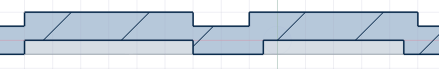
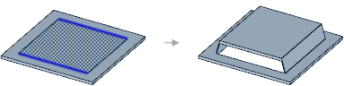
Shift faces or Offset faces: In the illustration below, the embossed area on the left was done with the Shift method and the embossed area on the right was done with the Offset method.
Remove top face: The top face is removed and the end faces are squared up.
Chamfer holes: Creates a chamfer on the top edge of inside holes.
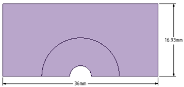
Select a sketched region to use as the form shape.
Closed sketches inside the region you select will become holes, as shown in the example below. The Chamfer holes option has been selected in this example:
(Optional) Use the Select Edges tool guide and select sides that you want open, like this:
Click the Complete tool guide to create the form or double-click to select the face and complete the form in one step.
Adding a Custom Punch Form to Your Design
Click
Forms in the Forms group on the Sheet Metal tab.Click Punch in the Custom Tools section at the bottom of the gallery.
Click the arrow at the bottom of the gallery to scroll down if you don't see the Custom Tools section.
Set the following parameters in the Options panel:
Through: The hole will go all the way through the sheet metal wall.
Partial: The hole will go only to the depth that you set in the Depth field.
Depth: How deep the punched hole should go into the sheet metal wall.
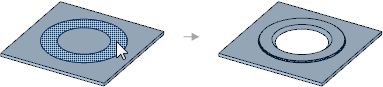
Countersink: The sides of the punched area are drafted at a 45° angle. The draft angle is measures across the hole and made so that its extents are outside of the sketched area.
Full: If you select Countersink, the inside walls of the hole are angled from the top of the hole to the bottom.
Partial: If you select Countersink, the inside walls of the hole are angled from D1 to D2 in the illustration below.
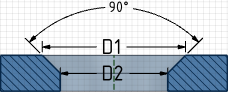
Diameter: The smaller diameter of a partial countersink (labeled as D2 in the illustration above). Only used if you select Partial.
Click the Complete tool guide to create the form or double-click to select the face and complete the form in one step.
Removing a Form From Your Design
Click the form to select it.
All faces that belong to the form are selected by default. You can scroll your mouse wheel if you need to select a single face of the form.
Click the Fill tool in the Edit section of the Design tab.