
| ANSYS Discovery SpaceClaim |
|
Encoded GD&T symbols understand their dimensional and situational context within the model. So, when their attachment references change in space or in type, the symbols update accordingly or become invalid.
GD&T is part of the Product and Manufacturing Information (PMI ) exchanged between CAD systems. The PMI Working Group recognizes two levels of information that can be exchanged in the context of explicit 3D geometric shape representation and associated PMI.
Representation information is pointed to by the definitions shown in the Structure Tree. The geometry that the definitions apply to are recognized as features which are displayed in the tree. Definitions which apply to the features are shown as sub-nodes of the features in the tree. This includes dimensions for features of size. All GD&T items in the Structure Tree are contained in the 'GD&T' folder as shown in the image below.
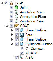
GD&T has its own Structure Tree folder.
Presentation information is the actual symbol shown in the graphics area and attached to geometry.

Representation stays with the object because it is part of its Structure. Presentation information is built from the representation.
So, when a solid with associated encoded GD&T is moved to a new component:
Both the ASME and the ISO standards are supported for GD&T. Set the standard in the General Detailing page of Discovery SpaceClaim Options. You can apply the standard to the current document or to all new documents.
The descriptions in this topic are based on the ASME standard.
To encode a GD&T symbol, you construct a Feature Control Frame, which consists of a rectangle divided into compartments containing:
Feature references
Prior to creating the symbol, you need to have the appropriate Datum Features  in the model.
The geometry to which a GD&T symbol is applied is usually called a "Feature". Features may be specified by:
After choosing a Characteristic Symbol and the geometry (usually called Features) to which the tolerance will apply, you will be asked to select the relevant Datum Feature references
An exception is Form tolerances, which do not use Datum Feature references.
When you first create a GD&T symbol, the default Characteristic Symbol is Position. Once you choose a different symbol, that becomes the default until you select another one.
Characteristic Symbols are shown in the table below.
Tolerance Type | Symbols | Applied To | |||
Form |
Straightness |
Flatness |
Circularity |
Cylindricity | Individual Features |
Line |
| Individual or Related Features | |||
Orientation |
Angularity |
Perpendicularity |
Parallelism | Related Features | |
Location |
Position |
Concentricity |
Symmetry | Related Features | |
Runout |
Runout |
Total Runout | Related Features | ||
Once you have selected the Datum Feature references, you are put in placement mode where:
tool to create any Datum Features to be referenced by the symbol. (Datum Symbols are encoded as well)
(see the table below)) cylinders (ASME Y14.5 Figure 4-34)After the symbol has been placed, you can add any appropriate modifiers by
When you select a symbol element, the mini-toolbar will present all relevant modifiers.
Their meaning and applicability are described in the relevant sections of ASME Y14.5 (2009) and ASME Y14.41.
Available Modifiers are shown below.
Symbol | Modifier |
| At Maximum Material At Maximum Material Boundary (When applied to a Datum Reference) |
| At Least Material Condition (When applied to a tolerance Value) At Least Material Boundary (When applied to a Datum Reference) |
| Translation |
| Projected Tolerance Zone |
| Free State |
| Tangent |
| Unequally Disposed Profile |
| Statistical Tolerance |
| Between |
| All Around |
| All Over |
Some notes about Modifiers:
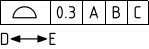
Between indicates that the tolerance applies across multiple features or to a limited segment of a feature between designated extremities.
The example below shows a profile tolerance between D and E. The system prompts you to select a direction and a first and last face to include (first and last can be the same face). It places labels based on the next available letters but you need to create notes pointing to the locations on the faces.
Select the Profile tolerance to modify
Choose Between from the mini-toolbar
Select an edge to set the direction of the limited region or group of features
Select the first face
Select the last face
Complete
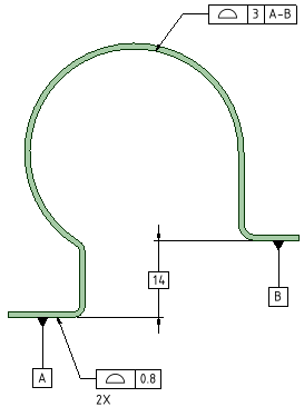
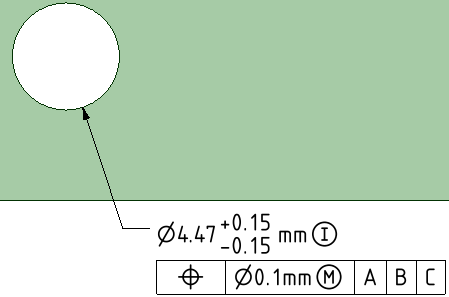
Diameter and width dimensions for Features of Size can have the Independency modifier added to the Dimension. This revokes Rule #1 in the ASME standard. Rule #1 establishes a boundary of perfect form at the MMC size limit. Rule #1 is also called the Envelope Rule.
To add the Independency modifier, select the dimension, and set the Suspend Envelope Rule property to True in the Properties panel.
An example is shown below.
In the ISO standard, the Envelope Rule is not applied by default. So, if you are using the ISO standard and want to apply the Envelope Rule, you need to set the Impose Envelope Rule property to True in the Properties panel.
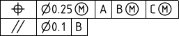
You can add segments to GD&T symbols in much the same way as they are initially created. This creates an FCF stack.
Instead of selecting geometry, you select the Characteristic Symbol of an existing GD&T symbol.
Based on which Characteristic symbol you wish to add, the system will limit which existing symbols are available.
For example, adding Concentricity to the position tolerance of a hole is invalid.
FCF stacks are sorted by tolerance value. The largest value is always in the first FCF and the values decrease as you go down the stack.
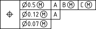
A Feature-Relating Tolerance Zone Framework (FRTZF) contains a single entry of a Characteristic Symbol followed by each tolerance and datum requirement, one above the other.
FRTZF applies to Position and Profile tolerances used with Patterns.
Each segment can have the same number of Datum Feature References or Less than the segment above it.
To create a FRTZF:
To set the FRTZF Datum Feature References:
Select the first secondary tolerance value
The mini-toolbar appears
The mini-toolbar options will adjust depending on which segment tolerance is selected.
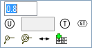
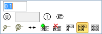
For patterns, you can create a Datum Feature Symbol that applies to a single member only, or the whole pattern.
In the Options panel, check the Use One Pattern Member Only option On to apply the symbol only to the selected pattern member. Check it Off to apply the symbol to the entire pattern.
The image below shows an example. For the entire pattern, the number of pattern members is included in the symbol.
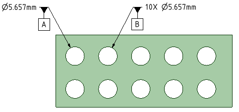
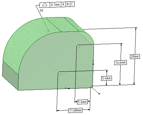
The Datum Reference Frame (DRF) consists of three mutually perpendicular planes inferred from three Datum Features.
Datum Features that comprise the DRF can be a combination of planes and cylinders.
The DRF is inferred from the Datum Feature References. This does not mean the references have to be three orthogonal planar features.
The XYZ coordinate system in the image above is the Datum Reference Frame formed by the three Datum Features A, B, and C.
When you select a DRF in the Structure Tree, it highlights in the Graphics Window. If the DRF has any unconstrained degrees of freedom (DOF), the DRF display in the graphics window is animated to show movement in the unconstrained DOF's.
DOF information is displayed in the Properties panel for a selected DRF. The constraints are established by default rules when the DRF is created. In some cases, you may want to override the defaults. Each Datum of the DRF can have it's constraints modified with a dropdown menu in the Properties panel of the DRF.
Selecting a DRF in the Graphics Window highlights it in the Structure Tree.
The DRF may not be valid if changes have been made to invalidate any of the symbols. Invalid Datum Features are marked with a Red 'X' in the Structure Tree.
You can Delete a DRF by selecting it in the Structure Tree like other Discovery SpaceClaim objects.
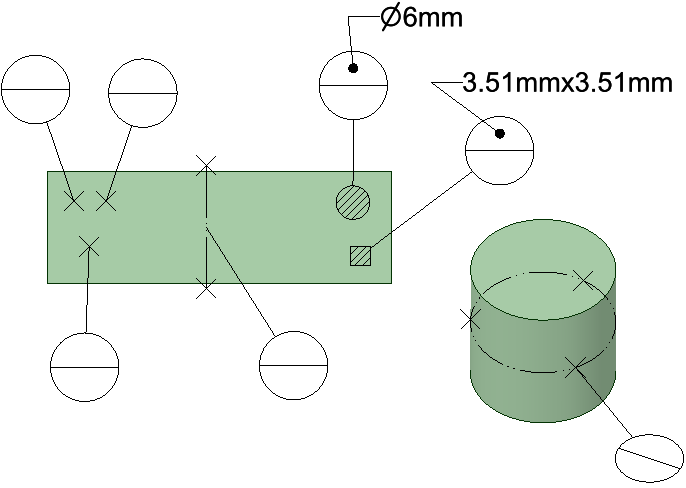
Datum Targets are Points, Lines and axes, or Areas used for establishing a datum. Because of inherent surface irregularities, the entire surface of certain features cannot effectively define a datum. Some examples are:
You can think of Datum Targets as representing contact between the part and a measuring gage or fixture. points represent contact with a pointed pin, or a pin with a spherical end. lines represent contact between a cylindrical part and a cylinder on the fixture. Areas represent contact with a flat-ended pin (either rectangular or circular).
The image below shows the different Datum Targets. From left to right they are, Point, Line, Area (rectangle and Circle), and the three points on the cylinder define a Datum Axis.
Datum targets are all created with a single pick point on a surface. The pick point locates the Datum Target as follows.
Datum Target Lines are created with a default Length and Orientation. To change either one, select the line and edit its Length or Orientation properties in the Properties Panel.
Datum Targets can be encoded into the model as Datum Features. Click on the Datum Symbol tool and select Datum Targets. They establish Datum Features when selected as follows:
Basic Dimensions locate the controlled features back to the Datum Reference Frame. They are generated automatically once the DRF is established. All you need to do is place them.
are available to switch between the different directions (X, Y, Z) and to change annotation plane.The image below shows Basic Dimensions for a Surface Profile tolerance.
You can recreate Datum Feature symbols and Feature Control Frames in the graphics window and drawing views from symbols listed in the Structure Tree.
If you select a Datum Feature in the tree, follow the same procedure but use RMB > Create Datum Feature symbol
Features that have encoded GD&T can be locked. Once a feature is locked, it can't be modified in any way that violates the encoded tolerance.
To Lock an encoded feature, select the feature in the Structure Tree and use RMB > Lock feature.
When a feature is Locked, the system runs checks after any modifications are performed to verify that the encoded tolerance is not violated. The modifications will preview but will snap back to the original geometry if any of the following are changed or removed.
To Unlock an encoded feature, select the feature in the Structure Tree and use RMB > Unlock feature.
Track Encoding  allows you to see the encoding status of your model as you add GD&T. The button has two parts. The top part of the button is a global ON/OFF switch to turn tracking On and Off. The bottom part of the button is a dropdown menu with two choices, which are both ON by default.
Reasons to use Tracking include the following.
| When the model is opened it looks like this. There is some GD&T already applied to the model but you do not know if it is encoded or not. | 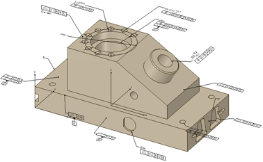 |
| Turn Tracking ON to immediately see what is encoded. In this example, all but one symbol is encoded. The non-encoded symbol is NOT dimmed. | 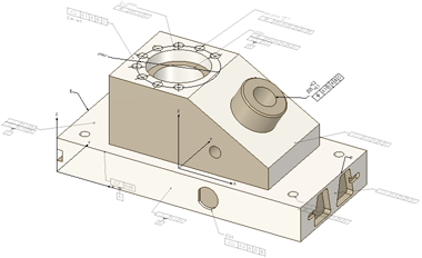 |
| If you turn Faces OFF, you can focus on just the symbols as shown here. | 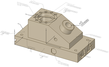 |
Copyright © 2004-2017 ANSYS, Inc. All Rights Reserved. SpaceClaim is a registered trademark of ANSYS, Inc.


