
| SpaceClaim Online Help |
|
Use the ![]() Convert tool in the Import ribbon group on the Sheet Metal tab to convert an existing design to sheet metal within SpaceClaim. You may need to convert if you imported regular geometry or if you moved a part to another component.
Convert tool in the Import ribbon group on the Sheet Metal tab to convert an existing design to sheet metal within SpaceClaim. You may need to convert if you imported regular geometry or if you moved a part to another component.
When you click the Convert tool and select a surface body of a design, the surface body automatically thickens into a sheet metal body at the default sheet metal thickness. This enhancement eliminates the need to redo a surface you may have sketched prior to converting the design to sheet metal. After you convert the body, you can use the Identify tool to call out forms, joggles, hems, etc.
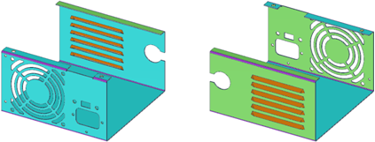
Walls, bends, junctions (only created, default-sized junctions, not imported junctions), and forms that were made in Sheet Metal are identified by color: Faces are blue, junctions are purple, forms are orange, partial bends are yellow, and edges of end faces that are not square are red. Identification is important because it allows the element to be unbent or flattened when you unfold the part.
See Converting a solid to a sheet metal part tutorial for a hands-on example with additional steps you may need to perform when you convert a part, such as adding reliefs and junctions.
Click ![]() Convert in the Import group on the Sheet Metal tab.
Convert in the Import group on the Sheet Metal tab.
The Select Bodies tool guide is enabled by default.
Select the body you want to convert.
You can Ctrl+click to select multiple bodies.
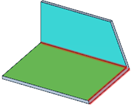
Walls, bends, and junctions (only default-sized junctions you created as sheet metal, not imported junctions) are automatically detected and identified by color. Faces that are not separated by the default thickness are not highlighted. Edges shown in red indicate end faces that are not square, as shown in the following figure.
Click the Assign Objects tool guide.
Convert hard edges to junctions:
Select the hard edges that you want to convert to the current junction type.
Clicking an edge shown in red creates a junction or squares up a sharp face. The edge you click to square a face determines the final length of the sheet metal wall.
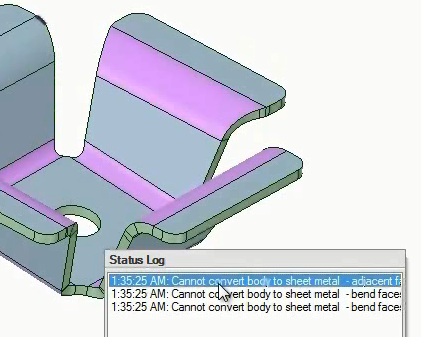
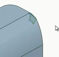
When you convert to sheet metal, faces that have problems are identified with error messages in the Status Log. Clicking on each message will highlight the problem with red blinking. In the example below,the message is selected and the problem is highlighted in the upper left corner of the leftmost image. A detailed view of the problem geometry is shown below in the rightmost image.
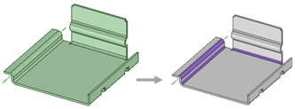
Converting a sheet metal design with bends automatically detected.
|
|
Use the Select Bodies tool guide to select the part(s) you want to convert to sheet metal. |
|
|
Use the Assign Objects tool guide to assign or change the junction types, reliefs, and notches. You can only select geometry that is appropriate for the tool guide. |
© Copyright 2015 SpaceClaim Corporation. All rights reserved.

