
| SpaceClaim Online Help |
|
Use the  Hole table tool from the Annotation
 ribbon group in the Detail tab to create a table that orders a design’s round holes by size (classified by duplicates) and labels the holes on a planar face. In a hole table, holes are sorted in order from left to right, then top to bottom. This feature works with holes only (threaded or non-threaded) including designs with hole patterns, but does not work with slots of any type.
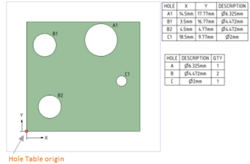
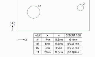
A Hole table displays in the Structure tree as an Annotation Plane. You can deselect the Annotation Plane checkbox to hide the Hole table. A Hole chart displays the quantity of holes in your design that have similar diameters. Once you create a Hole table, origin points, and X and Y axis labels, display as shown in the image below, and you can create a Hole chart:
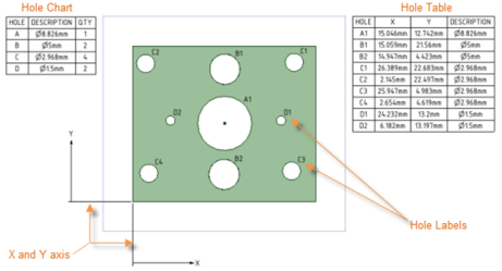
Holes with counterbores, countersinks, or fillets are shown in the table. Dimensions are taken from the intersection with the top plane and the hole.
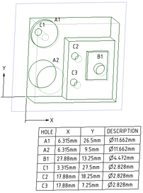
SpaceClaim uses all faces of the solid with the same orientation to collect holes for the table. Label editing works for holes that appear on multiple faces as shown in the image below.
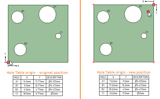
You can drag a Hole Table origin to move it. As shown in the image below, an origin displays as a red circle:
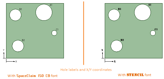
You can use the Font options in the Font group of the Design tab to format the font text properties of the X/Y labels and all hole labels, as shown in the image set below. For example, you might prefer text to display in a non-default font, or a Microsoft Windows 3.1 font, such as Modern, Roman, or Script. You can also change font text properties of hole tables that display for either single or multiple faces.
The axis or line font changes automatically to update to your selection.
The images below show samples of hole tables with different fonts used for hole labels and X and Y axis coordinates:
to adjust the number, width, or height of a table element.
When you change the size of a hole, the values in the table update, and the table re-orders and re-classifies the holes and rows of the table.
When you copy and paste a hole, the table updates to display a new row with the hole’s X, Y, and Description values.
After you drag a label to another position on the design, the table updates to the size and position of the new hole. To display your changes in a new table, right-mouse click and select Show Hole Table.
To remove a table or chart, select the table, right-mouse click, and select Cut.
© Copyright 2016 SpaceClaim Corporation. All rights reserved.