
| ANSYS Discovery SpaceClaim |
|
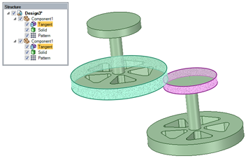
Assembly tools allow you to create proximity/arrangement conditions between components. These conditions constrain the components so they can't be moved in ways that violate the condition. In the animated example below, two cylindrical components (one large and one small) are constrained with a tangent condition. The large cylinder can be moved vertically without moving the small cylinder, but both cylinders move if either is angled because tangency between them must be maintained.
See the printable Assembly constraints reference chart  for descriptions of the constraints created between different combinations of geometry.

|
It is very important to note that, because conditions constrain movement, it is possible to create conditions where a desired movement is not possible. A constraint solver is used to calculate the degrees of freedom available for movement, and then minimize the (small) errors resulting from conflicts, if present. |
Assembly conditions are displayed in the Structure tree with the same icon as the condition tool chosen from the ribbon - one for each component in a matched pair of conditions.
An assembly condition that cannot be satisfied to a certain tolerance is shown with a small yellow triangle in the Structure Tree.

|
|
Objects must belong to different components for assembly conditions to be assigned. |
You can create multiple assembly conditions for your components.
When you use the Move tool on a component that is constrained to have only one degree of freedom, the move handle adapts to this and only activates the available movement/rotation axes.
|
|
The assembly constraint solver behaves differently than those in a history-based modeler. Read the important notes about assembly conditions in the next section. |
Once an assembly condition is applied to a component, the component is constrained as to translation or rotation, or both. For example, a block with one face aligned to another planar face, can move within that plane, and rotate on that plane, but cannot rotate out of the plane (so that the aligned faces are no longer parallel).
Since there is no notion of History, the order of adding assembly conditions is unimportant; all active constraints are evaluated at the same time. The constraint solver calculates the available degrees of freedom for components, and then solves for the least possible error. The manner in which it does this leads to some important considerations when assembling components.
base unit of meters. Converting to other unit systems will convert the error value accordingly.|
|
Even though there is no notion of history, there may be slight differences in the resultant error depending on the initial conditions and degrees of freedom. For example, applying constraints to two components that are initially close together will produce an error that may be different than if they are initially farther apart. Both error values, however, will be less than the error threshold of the solver. |
If all components are created and assembled in a way that there are no conflicting constraints, there will be zero error and all components appear perfectly aligned (see below for an illustration).
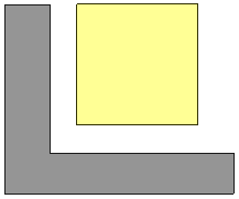
| A perfectly square block is to be assembled to a 90° L-shaped block so that it fits in the corner. |
|
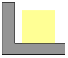
| The bottom face is aligned to the horizontal face. |
|
| The left face is aligned to the vertical face. |

|
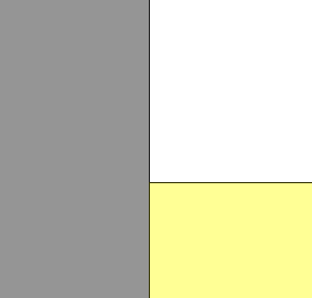
| Zoom in on the bottom-right corner and see perfect alignment. |

|
| Zoom in on the top-left corner and see perfect alignment. |
|
| HOWEVER; If the vertical face has significant draft, the bottom can be aligned but the vertical face cannot (or vice versa.) Doing so, would cause the bottom face to rotate out of alignment with the horizontal face. Because it is a large angular error, the internal threshold cannot be reached, and the Align condition is shown in the Structure Tree with a warning triangle.
|

|
|
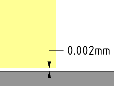
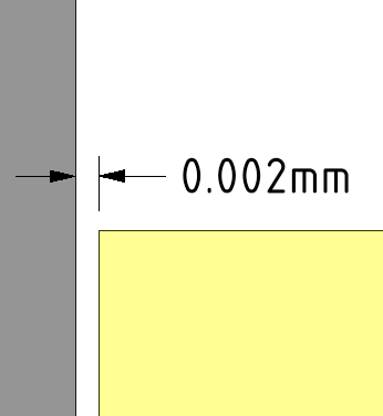
FURTHER; The square block looks the same in this example but the left vertical face has a small (0.01°) incline. This incline is smaller than the solver tolerance so the condition can be created. What actually happens is that the positions of both blocks are adjusted to minimize the alignment error. This is potentially non-intuitive, especially as many users expect that a previously-assigned Alignment would never be “violated” by a conflicting condition. |

|
| Zoom in to the bottom-right corner and you can see that a very small interference has been created, "doing the best it can" given the conflicting instructions. |
|
| The same is true at the top-left corner. |
|
EVEN FURTHER, in an unconstrained, unordered, error-minimizing system, the order of selecting components has no bearing on which one will move and/or rotate to satisfy the condition as it is added. The system attempts to calculate these so that the smallest overall change gets made in order to satisfy the newly added condition.
If a notion of order is desired, then it is recommended that you apply an Anchor condition to one of the components. The anchored component will remain stationary and the positional/rotational change will only affect the other component (and of course all components that are assembled to it.)
The following are useful techniques when working with assembly conditions.
Uncheck the assembly condition checkbox in the Structure tree to disable the assembly condition. Check the box to enable the assembly condition.
Click ![]() Select all conditions in the Options panel when an assembly tool is enabled.
Select all conditions in the Options panel when an assembly tool is enabled.
You can also select a single assembly condition in the Structure tree and press Ctrl+A.
Select the assembly condition in the Structure tree.
You can click Select all conditions in the Options panel when an assembly tool is enabled if you want to delete all conditions.
Press the Delete key or right-click and select Delete Assembly Condition.
Select the assembly condition in the Structure tree.
You can click Select all conditions in the Assembly Options panel to highlight all conditions.
You can use the following tools from the Assembly group to create assembly conditions:
|
|
Aligns two faces so they are tangent or aligns a face tangent with a line, point, or plane. Possible face types include planes, cylinders, spheres, and cones. |
|
|
|
Aligns two points, lines, planes, or combination of these elements. If you select a cylindrical or conical face, then the axis is used. If you select a spherical face, then the center point is used. |
|
|
|
Rotates components so the selected elements are oriented in the same direction. |
|
|
|
Locks the orientation and position of two components to each other. |
|
|
|
Constrains two objects so one of the objects rotates in response to the rotation of the other object. Gear conditions can be created between two cylinders, two cones, a cylinder and a plane, or a cone and a plane. |
|
|
|
Locks the position of a single component in 3D space. |
Copyright © 2004-2017 ANSYS, Inc. All Rights Reserved. SpaceClaim is a registered trademark of ANSYS, Inc.
