| DesignSpark Mechanical Online Help |
|
Use the Note tool to annotate your designs or drawing sheets. You can use this tool to create and edit notes. You can also project the note onto a sketch or onto a solid. Place the annotation plane on one layer and the note on another layer, then turn off layer visibility for the annotation plane to hide it. You can also create circular note text.

Notes are shown in the Structure Tree. Like curves, Notes can live in datum planes or drawing sheets. Unlike curves, they do not live directly in a part. So, in a part, you will not see a Notes folder.
Select the Note tool ![]() from the Annotation ribbon group in the Detail tab.
from the Annotation ribbon group in the Detail tab.
Mouse over the faces of your design to preview the eligible annotation planes. (In Sketch and Section mode, the sketch grid defines the annotation plane.)
Click a face to create the plane on which to place the note.
To create an annotation plane for a cylindrical face, select the cylinder's axis.
If you need to change the annotation plane, right-click and click Select New Annotation Plane from the context menu and select a new annotation plane.
Click to place the note on the plane.
Enter the text of the note.
 in the mini-toolbar to insert a symbol into your note at the cursor location.
 in the mini-toolbar to insert a dynamic field. Dynamic fields include current values from a variety of properties.
Adjust the orientation of the note by dragging the rotation handles.
For vertical notes, set the Stacked property to True.

Field codes can be included within a note. The text in field codes is variable text; in other words, the text within a field is tied to code, so if you change a field code in your note or drawing sheet, for example, a date format, the field automatically updates.
Some field codes are bi-directional; for example, adding the Scale field code to a drawing sheet enables you to change the scale by editing the note, or, change the scale by changing the value from the Scale drop-down in the Sheet Setup group in the Detail tab.
Click within the text of the note and place the cursor where you want the field to appear.
Right-click to display the mini-toolbar.
Click in the mini-toolbar to display the Insert Field window.
The Fields tab displays the properties available for insertion. (Document properties are those that appear in the Properties panel when you click the top-level design in the Structure tree.)
Select a value from the Category drop-down to filter the properties displayed in the Fields list.
If you click Selected Object, you can click any object in the Design window or Structure tree to make its properties available.
If you select Formula, you can enter an expression, and include any numeric fields within the expression.
Click a property in the Fields list.
Click the Format tab to format the text within the field.
The formatting options are based on the type of the property value. For example, strings can be formatted with upper case, lower case, initial capitals, or title case.
Click OK to insert the formatted, dynamic field into the note at the cursor location.
If the field is empty, check to make sure that the property you selected has a value by selecting the appropriate object and viewing the Properties panel.
Ctrl+drag a note to copy it.
You can also do the following:
Select the note to move, size, or rotate it.
If you select a single note, you can edit, resize, and rotate the note. If you select multiple notes, you can only move or change formatting.
To move the note box, mouse over the edge of the box until the cursor changes to  , then drag the note.
To size the box containing the note, drag the handles of the note box (the white circles).
To rotate the note, drag the rotation handle (the green circle). Press Shift to snap to angular increments.
Select the text of the note to reformat it.
Click a field to edit it. Changing the value of a string also changes it in the Properties panel.
Modify the note's properties in the Properties panel.
Circular Text
Type - Choose from:
None
Clockwise
Counterclockwise
Radius - Enter a radius for the note circle.
Cosmetic
Space - Choose from:
Model Space sizes the text based on the actual measurements of the objects in your design.
View Space sizes the text based on the view of the design in the Design window.
Mirrored - Set this property to True to display the text as if it is seen in a mirror. Notes seen from behind can appear 'backwards,' which can be confused as 'mirrored.' Setting this property confirms the Note is mirrored intentionally.
Stacked - Set this property to True to stack the text vertically instead of horizontally.
Flagnote
Flagnote is a drop-down menu of border shapes to put around the text.
Minimum width prevents the border from resizing automatically to fit the content of the note.

Position
Anchor influences the position and size of a note within a plane. Where you anchor a note determines the direction that the text will fill the note. For example, if you select the Left Top position, as you type, the expanded text box flows from left to right and top to bottom. The choices are:
Left Top
Left Bottom
Right Bottom
Right Top
Left Center
Right Center
Top Center
Bottom Center
Center
When moving a note or circular note, the note’s anchor (or circular note’s text center) now snaps to an edge, a sketch point, or an axis. Select the Move tool, and then select the note’s red anchor and drag it to an edge, sketch point, or axis. The red anchor will snap to the note’s anchor location that is closest to the drag point. The Anchor position updates in the Position group of the Properties panel as you move the anchor to a new location.
The Font group in the Detail tab has tools for increasing and decreasing text width.
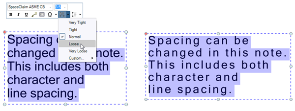
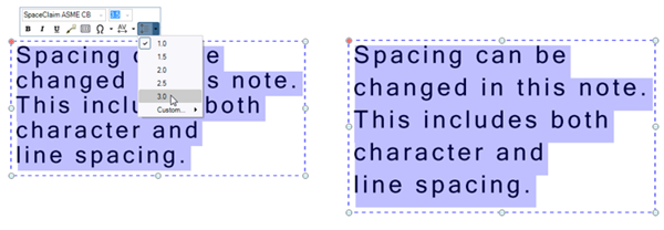
Character and Line spacing can be changed in Notes.
Any notes rotated differently are not affected by the above commands.
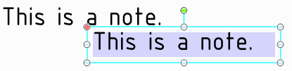
You can attach notes to other notes using the Attach Notes option in the RMB menu. The first note selected is the parent note (highlighted in blue) and any other notes you select become child notes (highlighted in dark blue).
option.When notes are attached, moving the parent note moves all the notes as one. However, moving a child note will move that note individually.
You can attach a note to the note fields of objects created with tools in the Detail tab. For example, Surface Finish symbols, Welding symbols, Datum Targets, Datum symbols, notes within a Symbol, and Dimensions are some tools that have note fields. Any notes can be attached to any other notes. Dimensions, however, can only be parent notes since they are attached to the model.
Free notes (those Not attached to the model with a leader) can be attached to a drawing view.
option.Moving a drawing view also moves any attached Free Notes.
Deleting a drawing view also deletes any attached Free Notes.
Create two layers, one for notes, and one for the annotation planes.
Place the note on one layer and the annotation plane on another layer.
Turn off the visibility of the layer that contains the annotation plane.
© Copyright 2020 Allied Electronics, Inc. All rights reserved.