| DesignSpark Mechanical Online Help |
|
You can choose constraint-based sketching to reduce the degrees of freedom (place constraints) on the drawing objects in 2D drawings and designs. Adding constraints restricts the type and range of movement of the objects, and links objects such that certain editing tasks on one drawing object will cause linked objects to be modified. Use tools in the Constraints group in the Sketch tab to add constraints to sketches.
Certain sketching tools included rudimentary tangency and coincident constraints (enabled with the Maintain Connectivity option), but these may be overridden during drawing editing. The tools in the Constraints group offer additional types of constraints which can be applied to any of the standard drawing objects (line, circle, arc, and so on) and are more robust.
To enable constraint-based sketching, select Enable constraint based sketching in the Advanced options in the DS Mechanical Options.
You can Save and Open models containing sketch Constraints. Designs that include Constraints will open in Sketch mode. Leaving Sketch mode will trigger the deletion of all constraint data. You need to save a copy of the sketch with constraints intact before solidifying if you intend to resume the design with constraints.
Note :Sketch constraints are active only in 2D sketch mode. If you switch to 3D mode, existing constraint data is deleted. If you expect to edit constraints as part of your design workflow, you must save a copy of the sketch with constraints before switching to 3D mode.
The following Constraints can be added to your sketch:


Notes:
For example:
First selection for Parallel: 
Second selection for Parallel: 
tool in the Modify group. All the rounds created this way maintain an Equal Radius constraint so that changing the size of one will change all of them.
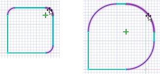
By comparison, in normal sketching, the rounds are equal radius during creation only. After creation, they do not maintain an association and can have their sizes changed independently.
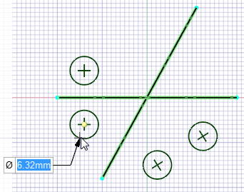
Adding Dimension constraints
constraint in the Constraints group. the cursor away from the object to position the dimension.
The normal behavior for applying and locating dimensions is observed. However, when applied as a constraint, if you attempt to edit one object, other objects may be modified to maintain the dimension constraint.
Notes:
constraints may be used to modify the size of the selected object. After creating the dimension constraint, double click to select the dimension and then modify the value. may be positioned vertically, horizontally, or aligned with the object. the cursor to position the dimension. length dimensions are supported – hold the Ctrl key while selecting the arc to create an arc length dimension. Move the cursor to position the dimension.
Adding an Equal Distance constraint
The Equal Distance constraint uses on-screen tool guides to determine the anchor and target distances, and to create the constraint. This is because more than one selection is often necessary to create the constraint.
tool guide active, select your moveable drawing object or pair of geometries to define the first dimension. 
A dimension line with the target symbol is added to the design page.

A dimension line with the anchor symbol is added to the design page.
The target object will be modified as required.
Note: A dimension between two lines will force the lines to be parallel.
Object States
When using constraint-based sketching, you can make sketch objects under-defined, fully-defined, or over-defined.

Creating Multiple Sketches With Constraints
You can create multiple sketches with constraints on the same sketching plane. The active Sketch node is shown in bold in the tree and the active sketch is highlighted in the design window.
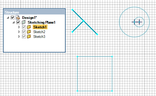
To activate a different sketch, select the Sketch node in the Structure tree and select Activate Sketch.
Note: Constraints may be applied within sketches on the sketching plane.
Creating a New Sketching Plane
option from the context menu.Existing sketches are solidified, and a new Sketch node is added to the Sketching Plane in the tree. The previous sketch remains active temporarily until you start sketching in the new Sketch.
Note: Coplanar Sketch Constraints can reside on different containing planes.
Viewing Constraints
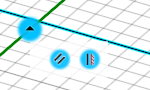
Select Show Constraint Tips in the Constraints group to view the constraints applied.
Hover over the constraint tip to see the type of constraint. The geometries involved will be highlighted dark blue.

If multiple constraints are applied, click the drop-down to see all the constraints applied.
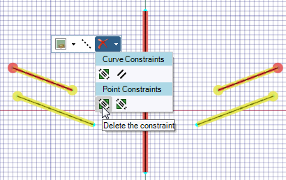
Deleting Constraints
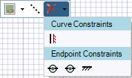
You can delete constraints using the Delete Constraint tool in the Constraints group or using the option from the mini-toolbar.
Using the Delete Constraint tool:
Select Delete Constraint in the Constraints group. The Delete Constraint tool is available when Show Constraint Tips is enabled.
Select the constraint to be deleted. In case of multiple constraints, click the drop-down and then select the constraint to be deleted.
Using the option from the mini-toolbar:
In addition to the context menu, a mini toolbar appears at the cursor location.

Note: If the drawing object is a point, the mini toolbar and drop-down will be simpler, containing only the point’s constraints. If multiple drawing objects are selected, the drop-down panel will contain the constraints common to all the selected objects.
Alternatively, click the red X to delete a constraint. The list of active constraints is shown.
Using Mirror With Sketch Constraints
Line to set up the mirror.

Lines, entities are mirrored about each mirror line whether they are perpendicular or not.
Notes:
Line, but the other Sketch tools are. Line. 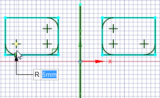
(Symmetry) constraints individually, click on an entity to open the mini toolbar. Individual constraints can be removed using the Delete dropdown menu.
Note: 1D Patterns and 2D Patterns are not supported for Constraint-based sketching.
Referencing Existing Geometry
It is possible to create constraints and dimensions to cross sections and edges that lie in the sketch plane. Such cross sections and edges are treated as reference curves and will not be changed. Creating a Sketch Constraint or dimension requires at least one non-reference curve to allow for the constraint to be satisfiable.
© Copyright 2020 Allied Electronics, Inc. All rights reserved.