| SpaceClaim Online Help |
|
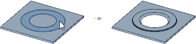
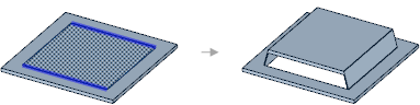
Use the  Forms tool in the Create group on the Sheet Metal tab to choose from a gallery of standard formed sheet metal details. Forms can be placed on any sheet metal face and can be placed on the edge of a face.
Select Forms in the Highlight group on the Sheet Metal tab to highlight all forms in your sheet metal design.
Click Forms in the Create group on the Sheet Metal tab.
Select a form in the gallery that opens below the tool icon.
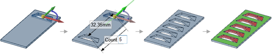
Change the form parameters in the Options panel .
.
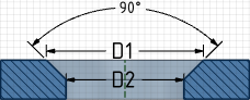
Hover over the illustration thumbnail in the Options panel to see a larger illustration with each dimension or value.
These parameters will be saved as properties for the form.
Change the Rotation angle in the Options panel, if available.
Click on a face to place the form.
If you want to dimension the position of the form, click the Place the form using a grid tool guide and select a face to place a sketch grid. You can then snap to the grid or hold the mouse over an edge and press Shift for dimensions to lines, points, and intersections
An outline of the form will be shown on the face. You can click again to reposition the form.
Click the Complete tool guide to create the form or double-click to place and complete the form in one step.
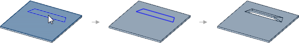
Sketch a profile at an endpoint of the edge.
Enter the Pull tool.
Click the Sweep tool guide.
tool guide.
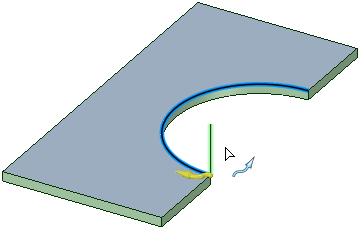
The vertical line will be swept along the arc to create the form.
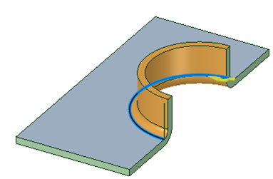
Notice that the sweep profile is a single line and an Inside Radius arc is automatically added to the profile, at the attachment point, to produce a bend. If you draw a tangent arc along with a line, then that arc determines the bend radius and overrides any inside radius automation that is done in the case of only a straight line.
Swept Edge Forms can be unfolded.
Click on the form to select it.
Change the parameters in the Sheet Metal section of the Properties panel.
The parameters in the Properties panel are the same as the parameters in the Options panel when you created the form. No parameters are shown for forms that can't be rotated or that don't have parameters.
You can also change the Flatten Form property for the component to change how the form is treated when the sheet metal part is unfolded. See Changing sheet metal part properties.
The following tool guides help step you through the process:
|
|
The Place the form tool guide is active by default. This tool guide allows you to place a form on any sheet metal face. |
|
|
The Place the form using a grid tool guide allows you to select a face for a sketch plane, and then you can place the form on the plane using the grid. You may want to use this tool guide to help accurately position your form. You can use any dimensioning methods normally available for a sketch grid. |
|
|
The Select a face tool guide allows you to select the face that will become the form when you create a user-defined form. |
|
|
The Complete tool guide creates the form and allows you to place more forms until you exit the tool. |
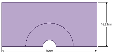
Each form has its own options for the form's dimensions. These dimensions are shown in the thumbnail illustration in the Options panel. Hover over the thumbnail with your mouse to see the full-size image.
Most forms have the following options:
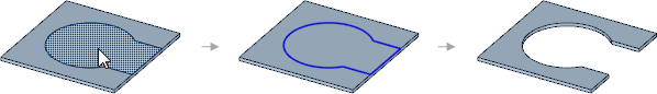
Creating a user-defined punch form on the edge of a face removes material from the edge.
You can create a pattern of forms, and the forms are recognized by the Convert tool.
© Copyright 2014 SpaceClaim Corporation. All rights reserved.
 To add a countersink or special form