
| SpaceClaim Online Help |
|
A beam is a long, thin object with a constant cross-section. Defining objects as beams, rather than modeling them as solid geometry, simplifies the model and analysis.
Create objects to define the beam path
One or more of the following methods can be used in the same design:
Sketch curves: Use any of SpaceClaim's sketching tools to create straight or curved segments and then assign beam profiles to them. These sketch curve beams can then be modified just like any curve in SpaceClaim using the Move , Pull, Select, Scale, Bend, Extend, and Trim tools. This method is a straightforward, lightweight way to create beam structures.
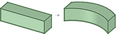
Edges of a solid or surface: Use this method when you have solid geometry that you want to reference for the beams. For example, to create a simple rectangular cage of beams, sketch a rectangle, pull it into a solid, and assign beams to all of the edges. If you change the solid, then the beams will dynamically update to match the location and length of the edges. Any of SpaceClaim's modeling tools can be used to create sophisticated geometry changes that drive changes to the beam structure.
For example, beams are assigned to the edges of the rectangular part shown below, and then the edges are bent. The beams are automatically updated when the solid is changed.
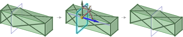
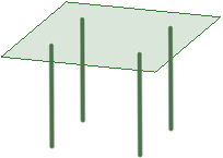
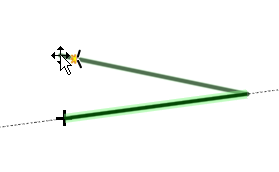
Two points or midpoints in a model: You can use any two points in a model to define a straight beam segment. Planes can be used to create "stages" or additional locations for defining beams to or from. A beam can be created to the intersection point of any plane with any edge. When a defining plane is moved, any associated beams dynamically update their locations. You can create sophisticated tower and truss structures using this method, and the structures will be easily adaptable to unforeseen design changes.
In the example below, one end of each diagonal beam was created at the intersection of the plane and the solid. The beams change when the plane is moved.
This tool enables you to add a profile to your structure.
.
 | More than one beam can reference the same profile, so the characteristics of all beams that use that profile will change if you edit the profile. |
The Create tool is enabled when you select a profile, which adds the profile to your design document. This tool enables you to create the beam path.
Select edges or points to define the path:
Chain tool guide and then select an edge or curve, or click on a series of points to create the path.You can use intersection points and midpoints on edges and other beams. Click on the small triangles on the ends and midpoint when you hover over an edge or beam.
See Creating a beam.
A Beams folder is created for the beams and a Beam Profiles folder is created for the profiles in the Structure tree:
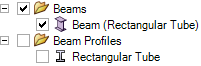
The profile name is displayed in parentheses after the beam name in the Structure tree.
If you have already modeled the beam you can convert it to a beam object. See Extracting a beam from a solid.
If you send a design with beams to ANSYS, the following is sent for each beam object:
You can import groups from a beam profile into your design document, which makes them available to drive changes within ANSYS. The groups are named based on the profile name, as <profile name>_<group name>.
Beams can share topology with surfaces when
The end point of the beam lies on the surface:
The path of the beam lies in the surface.
The beam intersects a surface at a point.
The beams and surfaces must be in the same component, the component must be set to share, and the mixed import option in Workbench must be set to lines and surfaces. See Shared topology in ANSYS for more information about shared topology.
The following table shows how beams, sketch lines, and edges look when they are highlighted and selected:
|
Highlighted |
Selected |
Selected and highlighted |
|
|
Beam |

|

|

|
|
Sketch |

|

|

|
|

|
|
You can use Copy and Paste to make copies of beams.
Dragging to move an endpoint.Beams can also be copied in the same way a Curves, by using Ctrl+Alt when dragging the endpoint.
© Copyright 2016 SpaceClaim Corporation. All rights reserved.