
| SpaceClaim Online Help |
|
This tutorial will teach you how to define midsurfaces.
Click on the following link and save the file on your computer: w8872.scdoc.
Open the document in SpaceClaim.
The design looks like this:
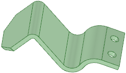
We will use this design to show basic midsurface creation.

|
If you are using the online version of the help, the model will be downloaded as a zip file. You need to save it to your disk and change the file extension from ".zip" to ".scdoc" |
First you will define the midsurface by selecting offset face pairs.
You should read Creating midsurface faces to become familiar with the Midsurface tool before you continue.
The four tool guides for midsurface are:
|
|
Select Faces tool guide is active by default. This tool guide allows you to select a pair of offset faces, and all other face pairs with the same offset distance are automatically detected. |
|
|
Add/Remove Faces tool guide allows you to select additional faces to offset or remove detected face pairs from the selection. |
|
|
Swap Sides tool guide allows you to switch the face pairs. You may need to do this when the sets of detected colored faces are not grouped cleanly. |
|
|
Complete tool guide creates the midsurface faces. |
Click ![]() Midsurface in the Define group on the Prepare tab.
Midsurface in the Define group on the Prepare tab.
The Select Faces tool guide is active by default.
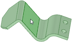
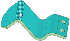
Select the face shown here:
After you select the first face, SpaceClaim will filter the selection and will only allow you to click on parallel faces, or faces that produce an offset.
Select the offset face, shown here:
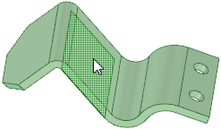
This is the only face you can select.
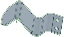
All surfaces with the same thickness will be identified on the part and highlighted in blue:
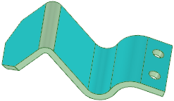
As you can see, one round does not have the same thickness and is not identified as an offset pair. Faces that look like offset pairs might not be identified as a midsurface because of errors in translation, or when the part was not modeled with an offset face.
Click the Add/Remove Faces tool guide if it is not already active (it should be).
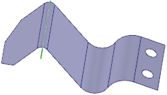
Select the round face:
This face will now be included when the midsurface is created.
Note : Faces only need to be identified on one side of the model.
Now you can finish defining the midsurface.
Click the Complete tool guide.
The solid is temporarily transparent so you can see the newly-created midsurface.
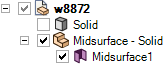
For a better view of the midsurface, hide the solid and expand the Midsurface component in the Structure tree, like this:
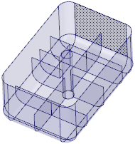
Now let's try a more complicated example.
Click on the following link and save the file on your computer: Midsurfacing.scdoc.
Open the document in SpaceClaim.
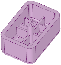
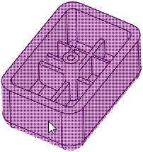
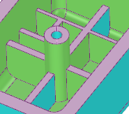
The design looks like this:
|
|
If you are using the online version of the help, the model will be downloaded as a zip file. You need to save it to your disk and change the file extension from ".zip" to ".scdoc" |
Click ![]() Midsurface in the Define group on the Prepare tab.
Midsurface in the Define group on the Prepare tab.
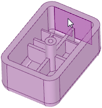
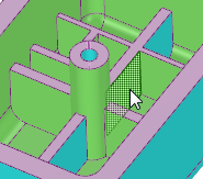
Select the face shown here:
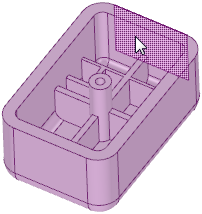
Now select its offset pair:
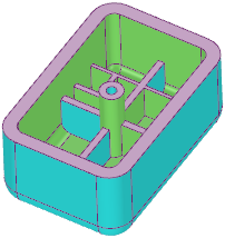
The outer faces of the part will be identified as offset pairs:
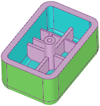
The base side of an offset pair is highlighted in blue and the offset side is highlighted in green. Midsurfaces are generated from the blue, or base, faces.
The inside ribs have a different thickness or offset from the outside walls, so we have to add them to the selection. We can do this using the Select Faces tool guide.
Click the Select Faces tool guide.
You can also hold Ctrl and this tool guide will become active.
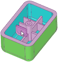
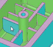
Select one of the inner ribs:
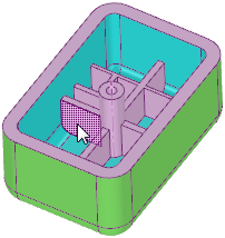
And select its offset pair:
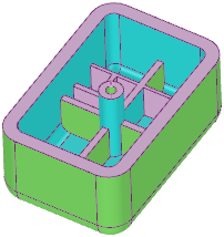
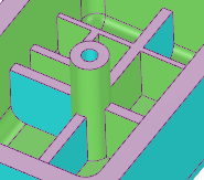
Most of the inside faces are now highlighted:
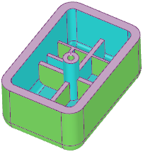
Continue selecting face pairs until your design looks like this:
Although we now have all of the face pairs selected, there is a more efficient way to select the offset face pairs in designs like this.
Click in white space in the Design window to clear your selection.
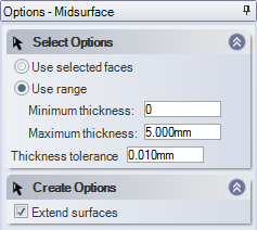
Select Use range in the Options panel and make sure the minimum and maximum thickness values are set like this:
Click on the solid:
All face pairs with offsets between the minimum and maximum thickness are selected.
If you zoom in, you'll notice that the base and offset sides on the ribs are not highlighted correctly. You can use the Swap Sides tool guide to change the base and offset sides. This is important because the midsurfaces are created from the base (blue) face. The offset face (green) is only highlighted so you can see it as you define midsurfaces.
Click the Swap Sides tool guide.
Select the first incorrect face:
Its highlighting changes from blue to green.
Select the other incorrect face:
Now all inner faces are highlighted correctly as base and offset faces.
Click the Complete tool guide to finish defining the midsurfaces.
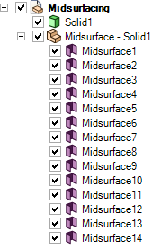
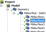
Notice that the midsurfaces are created in a new component in the Structure tree:
In addition to normal face properties, a midsurface has a thickness property that is sent to ANSYS and applied to the shell element.
Hide the solid in the Structure tree.
Select a midsurface face:
The Properties panel displays the properties for the face:
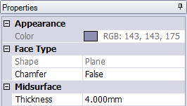
The Thickness property is in the Midsurface section of the panel.
The midsurfaces are ready for analysis in ANSYS Workbench.
Click the ANSYS Workbench button in the ribbon bar to send the current model in SpaceClaim to a new project in Workbench.
Everything that is visible in the Design window will be sent, so hide the solid so it will not be sent to ANSYS.
Go to Workbench and click on one of the midsurfaces under Geometry in the project:
Look in the Properties panel (below the structure tree) and you will see that a thickness is assigned to the midsurface. This is the thickness from the original solid in SpaceClaim.
Generate a mesh:
Right click Mesh under the project and select Generate Mesh.
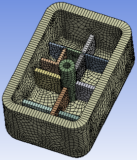
Workbench will use the thickness property assigned to it to give the model the proper mesh.
In this tutorial you learned how to
midsurface properties in SpaceClaim and ANSYS© Copyright 2016 SpaceClaim Corporation. All rights reserved.


