
| SpaceClaim Online Help |
|
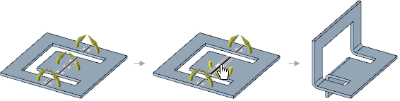
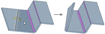
The Sheet Metal Bend tool works similar to Split , and is used to create bends in a sheet metal flat or unfolded part. You can bend along a sketch curve on the sheet metal face, bend perpendicular to an edge, or bend between two points.
You can also place multiple bend lines along a surface. Existing in-progress bends, that are not yet bent (flipped) remain de-selected as you place one or more new, additional bend lines along the sheet metal surface.
Click the ![]() Bend tool in the Create group on the Sheet Metal tab.
Bend tool in the Create group on the Sheet Metal tab.
The Create Bend option is enabled in the Bend Options panel.
(Optional) Modify the following values in the Bend Options panel:
Bend angle: The angle of the bend.
When selecting on an edge to create a bend angle, modifying the Bend Angle option propagates to the pull edge handles immediately.
Bend radius: The inner radius of the bend.
When a Bend Table is applied to the part, Bend radius is changed to Tool radius and the input becomes a dropdown list of available radius values from the table.
Die width: The width of the die. This changes to a dropdown list of available widths when a Bend Table is applied to the part.
Bend Allowance: Value to use for calculating the flat length of the bend.
Bend Deduction: Value to use for calculating the flat length of the bend.
Click on a sketch curve on the sheet metal face. The bend will be made across the full length of the face, regardless of the length of the sketch curve.
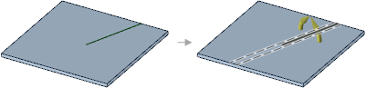
Click the Complete tool guide to create the bend.
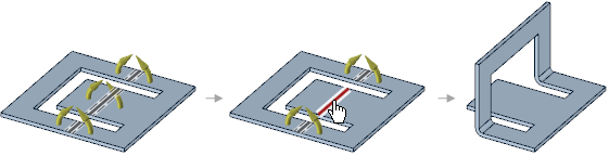
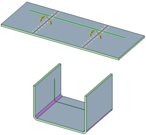
Follow the same steps you would use for creating a single bend.
Select curves in multiple components. The curves can belong to one component but lie on a face of another component. For example, curve 1 belongs to component 1, but is sketched on the face of component 2.
Click the Complete tool guide to create the bend.
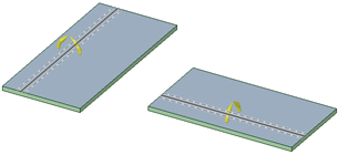
Click the bend line to cycle through bending up and bending down.
Clicking a bend segment until the bend line turns red removes the segment from the bend.
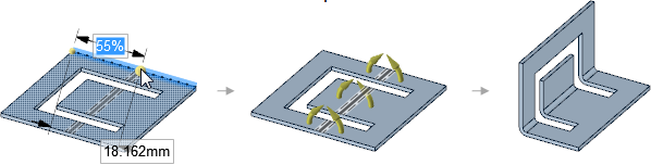
The dashed lines to either side of the bend line show the extents of the bend allowance area, based on the radius set by default or overridden by the user in the options area.
If necessary, you can click an empty location in the Design window while a tool guide is active to clear the bend line and activate the Select Cutter Point tool guide.
The following tool guides help step you through the process. Use the Tab key to cycle through them. As soon as the tool guide switches, the cursor may change to reflect the active guide.
|
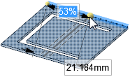
Select Cutter Point: Click a point on an edge to create a bend that is perpendicular to the edge at the point. Press Tab to enter a value for the percentage or distance from the bend to the endpoint along the edge. |
|
|
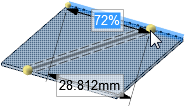
Select Two Cutter Points: Click a point on one edge and a point on another edge to create a bend between the points. You can see a preview of the line as it extends to the second edge before you click on it. Press Tab to enter a value for the percentage or distance from the bend to the endpoint along the edge. |
|
|
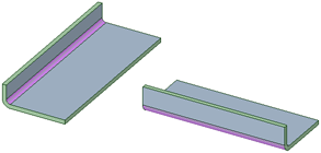
Select Anchor Point: Select the face you want to remain fixed when the body is bent: |
|
|
Select Curves: Select curves to be wrapped around bends. |
 |
The following tool guides help step you through the process. Use the Tab key to cycle through them. As soon as the tool guide switches, the cursor may change to reflect the active guide.
|
|
The Select Cutter Point tool guide is active by default. This tool guide creates a bend that is perpendicular to the edge at the point you select. |
|
|
The Select Two Cutter Points tool guide allows you to select a point on one edge and a point on another edge to create a bend between the points. |
|
|
The Select Anchor Point tool guide allows you to select the face that will be fixed when the body is bent. |
|
|
Click the Complete tool guide to create the bend. |
|
|
Use the Create Bend option to bend a sheet metal face along a line. |
|
|
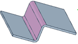
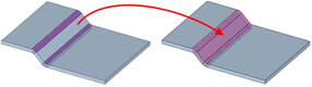
Use the Create Joggle option to create a joggle bend in a face. |
|
|
Use the Create Bead option to create a bead along a curve on a face. |
© Copyright 2016 SpaceClaim Corporation. All rights reserved.
 To add bend steps
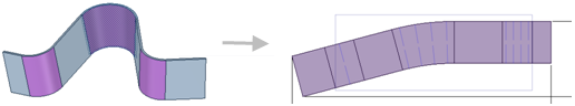
 Create Joggle option in the Bend Options panel.
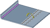
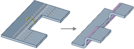

 Create Bead option in the Bend Options panel.
 Bend tool guide to complete the bead.


