
| SpaceClaim Online Help |
|
Use the Spline tool to sketch splines in 2D or to draw splines between points on objects in 3D. A spline is a continuously curved line, without sharp boundaries (that is, without vertices). Splines can become edges when you pull your sketch into 3D with the Pull tool. Sweeping along a spline in 3D lets you create smooth, curvy shapes.
The sketch grid must be visible in the workspace before you can draw.
Click ![]() Spline in the Sketch group.
Spline in the Sketch group.
If a sketch plane is not active, click on an object or objects in the Design window to make a sketch plane.
Click to set the first point of the spline.
Hold Alt and click to set the point if you want it to be tangent with an adjacent sketch or edge. When highlighting the vertex (which is actually an end point of one of the intersecting edges which has influence at the time) scroll the mouse wheel to select other adjacent edges with which to set the tangent vector direction, as previewed by the green tangency symbol.
Click to set the next points of the spline.
You can Dimension spline points by entering the coordinate distance from the start point to each point, or dimension each point relative to another sketch object.
End the spline:
Double-click to set the end point of the spline.
Hold Alt and click to make the end point tangent with an adjacent sketch or edge.
Right-click and select Finish Spline.
Connect the end point to the start point.
Click any other tool (except the Clipboard and Orient tools).
The following options are available for every sketch tool:
Cartesian dimensions: Select a point in a sketch and then click this option to see Cartesian dimensions from the point. Cartesian dimensions show you the X and Y distances from the point you select. If you don't have a point selected, it shows you the X and Y distances from the origin.
Polar dimensions: Select a point in a sketch and then click this option to see Polar dimensions from the point. Polar dimensions show you an angle and a distance from the point you select. If you don't have a point selected, it shows you the angle and distance from the origin.
Snap to grid: Select this option turn snapping on or off while sketching. The cursor will snap to the minor grid spacing increment while you sketch. The defaults are 1mm for Metric and 0.125in for Imperial units. See Units options to change the minor grid spacing.
Snap to angle: Select this option to turn angle snapping on or off while sketching. The cursor will snap to the angular snap increment while you sketch. The default is 15 degrees. See Snap options to change the angular increment used for snapping.
Create layout curves: The sketch curves are created as layout curves. If you move the design to a drawing sheet, with Sketch mode selected you must select the Create layout curves checkbox again in the Sketch Options group of the Options panel in order to create layout curves on the drawing sheet. See Layout Curves.
Curve Fitter Options: If the Sketch plane passes through a Mesh object, the system will fit curves through the facet points. Lines are displayed green and arcs are displayed blue. The following options apply to the system-generated curves.
Fit curves - Uncheck this option if you do not want the system to fit curves through the points.
Tolerance - Determines how many points will be found, which also determines how many curves will be created. The smaller the tolerance, the more points will be found and the curves will be generated.
Auto-merge - When checked On, the system will merge lines and arcs to form splines. Splines are displayed pink.
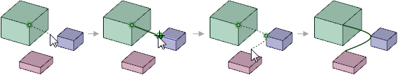
Sketching a spline between points in 3D
© Copyright 2016 SpaceClaim Corporation. All rights reserved.
 To draw a continuous spline