Hide All
Use the ![]() Move tool to move any object in 2D or 3D, including drawing sheet views. The behavior of the Move tool changes based on what you have selected.
Move tool to move any object in 2D or 3D, including drawing sheet views. The behavior of the Move tool changes based on what you have selected.
-
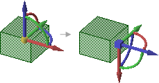
If you select an entire object, such as a solid, surface, or sketch, you can translate or rotate the object.
-
You can move one side of a solid, surface, or sketch to enlarge or reduce the size of the object.
-
If you move an object into another object in the same component, the smaller object is merged into the larger one and receives the larger object's properties.
-
Moving a component moves everything contained within the component.
-
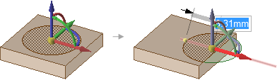
You can move a circular edge of a flat surface the same way you move a circular sketch curve.
-
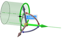
Moving the apex of a cone changes the height. Anchor the Move tool to the outer face to scale the cone.
When you move a component that has been assembled using assembly constraints, the Move handle is positioned at the constraint and the axes that are constrained are disabled. If the assembly constraints only allow movement in one direction, then that direction will be automatically selected. For example, if you move a component with a Center Axes assembly constraint, the Move handle is positioned on the axis and you can only move the component in directions that will keep the axes aligned.
 |
If the Move handle appears disabled, check the Structure tree to determine if an assembly condition exists for the component you are trying to move. |
Offset, mirror, and coaxial inferred relationships also affect Move.
|
If you entered the Design tab with sheet metal features selected, the Move tool will work as it does in Sheet metal. To work as usual, right click on the sheet metal part in the Structure tree and choose Suspend Sheet Metal in the context menu. |
To Move objects
-
Click
 Move in the Edit group on the Design tab.
 -
Select the object(s) that you want to move.
-
Select the following options:
- Move grid: Select this option to move the sketch grid.
- Ruler: Once you select an axis on the Move handle, select this option and click an edge or face to anchor the ruler. The ruler is oriented along the selected Move handle axis. Enter a value to use the ruler to dimension the move.
- Create patterns: Select this option if you want to create a pattern by dragging selected objects with the Move tool. Dragging creates a copy of the selected object, moves it to a new location, and creates a pattern relationship. Select the Maintain orientation option to keep the initial orientation of the original object when you rotate or translate the pattern. See Creating a pattern.
- Detach first: Detach the selected protrusions and depressions, move them, and reattach them at the new location.
- Maintain sketch connectivity: Keeps the connections between a sketch curve and other curves that share its end points. If you deselect this option and move a sketch curve, the curve will move independent of other curves.
-
Remember orientation: Sets the orientation of the Move tool for the object. The orientation is only remembered for the current session. You can change the Move handle orientation by using the Direction tool guide, holding Alt and selecting a reference object, or by dragging a ball on the Move handle's axes. You can select the following options in the drop-down list to the right of the option:
- Default: The Move handle orientation is determined by the object(s) you select.
- Global: Saves the current Move handle orientation, and this orientation is used for all objects.
- Per Object: Saves the current Move handle orientation for the selected object. When you select the object again with the Move tool active, the Move handle will be oriented at its saved orientation.
-
Click an axis and drag in that direction to move the selected object.
A line extends from the Move handle axis to indicate the direction you selected for movement.
If the move fails, the Move handle is repositioned to the last valid location and orientation. If you are trying to move a protrusion surrounded by round faces, you may need to fill the rounds.
-
You can also Alt + select a plane between Move handles to invoke free drag movement within that plane. Place the Move tool on any movable object and then hold the Alt key. Quarter circle planes appear between the Move handles. Selecting one changes the cursor to a free drag cursor and allows free movement within the plane. Select any Move handle to disable the free drag.
|
The cursor does not need to be on the axis to move the selected object. In fact, you may find it easier to control the move if you drag some distance from the entity and the Move handle. |
Moving a protrusion with rounds that intersects with a stepped solid with the Detach first option
Moving a circular edge along a surface
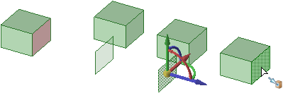
Moving an imprinted face off of a solid face creates a surface.
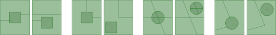
Moving imprinted edges on a face, and other intersecting imprinted edges are adjusted as needed. The examples above show how the edges are adjusted when the imprinted areas are moved.
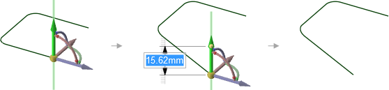
Moving the end point of a line segment that has a tangent arc on its other end changes the arc so that it remains tangent to the line segment as you move its end point.
 To move relative to other objects
-
Snap to a co-planar face: Hold Shift while dragging to snap to co-planar faces when you have the Move handle anchored to a planar face.
-
Move an object up to another object: Click the Up To tool guide to move objects so the center of the Move handle is adjacent to the object.
-
Orient an object to another object: Select the object to move and a Move handle axis, then click the Orient to Object tool guide and select a second object. The selected object will be rotated so the selected Move handle axis is aligned with the second object.
To change the anchor location of the Move handle
-
Drag the yellow center sphere on the Move handle
-
Click the Anchor tool guide and select the face, edge, or vertex on which to place the Move handle.
-
You can also click the Origin
 tool in the Insert tab to insert an origin anywhere in your design that you want to anchor the Move tool.
The yellow center sphere turns into a blue cube when the Move handle is anchored.
To change the direction or trajectory for the move
-
Drag one of the small balls on the rotational axis to reorient the Move handle, or dimension the orientation by typing the rotation angle while you are dragging, then pressing Enter.
-
You can also Alt+click a point or line, or click the Move Direction tool guide, then click a point or line, to orient one of the Move handle's axes toward that point or along that line.
If you Alt+click a trajectory, you can move along the trajectory. Ctrl+Alt+click to add contiguous lines or edges to the trajectory.
If you Alt+click a plane, the direction of movement is set perpendicular to the plane.
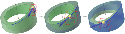
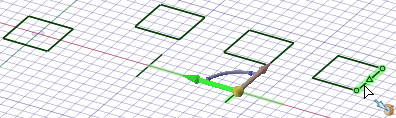
Normal to Surface - While moving the diamond along the selected trajectory, Ctrl+Alt+click the face of the cylinder to set the orientation of the diamond normal to the cylinder.
-
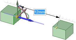
Follow the steps to move an object.
-
After you click an axis on the Move handle, click Ruler in the Options panel.
-
Click an edge or face to anchor the ruler.
The ruler is oriented along the selected Move handle axis.
-
Type a distance and press Enter.
To copy an object using the Move tool
-
Press Ctrl to copy the object selected for movement and place it at the location at which you drag or dimension the move.
You can press the spacebar to dimension the move.
-
Double-click the Up To tool guide to make multiple copies of the selected object. To exit this mode, click on another tool or in empty space in the Design window.
Copying the red face multiple times by double-clicking the Up To tool guide to keep it active for more than one move
Making copies by double-clicking the Up To tool guide also works with sketches
Tool guides
Within the Move tool, there are several tool guides that let you specify the behavior of the Move tool:
|
|
The Select tool guide is active by default. When this tool guide is active, you can select faces, surfaces, solids, or components within the Move tool. |
|
|
Click any object with the Select Component tool guide to select the solid to which the object belongs. If the solid is the only object in its component, the component will be selected. |
|
|
Select a point, vertex, line, axis, plane, or planar face with the Move Direction tool guide to orient the Move handle and set the initial direction of the move. (The object will not move until you drag.) |
|
|
Select a set of lines or edges with the Move Along Trajectory tool guide to move the selected objects along that trajectory. For best results, perform Moves along trajectories in small increments. If the object to be moved is a protrusion, it will be detached, then reattached in the new location. When you move a protrusion along a trajectory, rounds are automatically removed. Ctrl+Alt+click a face to control the orientation of the object being moved or patterned along. |
|
|
Select an object, then use the Anchor tool guide to select the face, edge, or vertex that will anchor the move. You can anchor the Move handle to a temporary object, such as the intersection between two axes by Alt+Shift+clicking the two objects. |
|
|
Select an object, then use the Fulcrum tool guide to move other objects around it. Select a pattern member to anchor it, or select a component to explode an assembly. See Moving with the Fulcrum tool guide. |
 |
The Move radially about axis tool guide allows you to select an axis to move the selected objects radially about. Once you select an axis, the Move handle will reorient to have one axis parallel to the move axis and one axis in the radial direction. |
|
|
Once you select the object to move and a Move handle axis, use the Up To tool guide to select the object you want to move up to. If a Move handle axis is selected, the Move is limited to that direction. If no handles are selected, the object is translated until the center of the Move handle lies on the selected reference. (A move handle must be selected to move up to the axis of an origin.) In a linear move to an intersecting object, the center of the Move handle is moved to the selected object. If the two objects do not intersect, the first object is moved along the desired direction up to the closest point to the second object. You can use this tool guide to:
You can double-click the Up To tool guide to keep it active. While the tool guide is active, it will copy faces and surfaces instead of moving them. To deactivate the tool guide, click it again, select another tool guide, or exit the Move tool. |
|
|
Once you select the object to move and a Move handle axis, use the Orient to Object tool guide to click an object. The selected object will be rotated until the selected Move handle axis is aligned with the clicked object. You can also use this tool guide to rotate the sketch grid in Sketch and Section modes. |


Options
The following options are available in the Move tool:
- Move grid: Select this option to move the sketch grid.
- Symmetric Move: Select this option to move symmetrically.
- Measure: Opens the Measure tool. Selecting a measurement result returns you to theMove tool. When you select move direction, the measurement value is displayed in a dimension box with an arrow pointing to the measured object. Modify the value for a one-time adjustment of the model or create a Measurement Group which can be modified at any time.
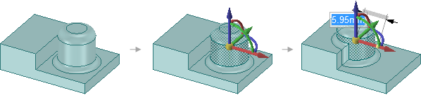
- Ruler: Once you select an axis on the Move handle, select this option and click an edge or face to anchor the ruler. The ruler is oriented along the selected Move handle axis. Enter a value to use the ruler to dimension the move.
- Maintain orientation: Select this option to maintain the orientation of the object when rotating or moving along a trajectory.
- Create patterns: Select this option if you want to create a pattern by dragging selected objects with the Move tool. Dragging creates a copy of the selected object, moves it to a new location, and creates a pattern relationship. Select the Maintain orientation option to keep the initial orientation of the original object when you rotate or translate the pattern. See Creating a pattern.
- Detach first: Select this option to detach selected protrusions and depressions, move them, and reattach them at the new location.
-
Maintain sketch connectivity: Keep the connection between a sketch curve and other curves that share its end points. If you deselect this option and move a sketch curve, the curve will move independent of other curves.
-
Keep beam fixed: This option is for beams and causes the beam to remain fixed while the profile becomes offset from the beam. See Moving beams.
-
Remember orientation: Sets the orientation of the Move tool for the object. The orientation is only remembered for the current session. You can change the Move handle orientation by using the Direction tool guide, holding Alt and selecting a reference object, or by dragging a ball on the Move handle's axes. You can select the following options in the drop-down list to the right of the option:
- Default: The Move handle orientation is determined by the object(s) you select.
- Global: Saves the current Move handle orientation, and this orientation is used for all objects.
- Per Object: Saves the current Move handle orientation for the selected object. When you select the object again with the Move tool active, the Move handle will be oriented at its saved orientation.
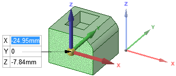
- Enter XYZ coordinates: This option allows you to enter X, Y, and Z distances to move relative to the World Origin. When you select the option, the Move handle re-orients to be parallel to the World Origin and displays X, Y, and Z input panels.