


Constraint Types
- Dimension

- Coincident

- Midpoint

- Concentric

- Fixed

- Horizontal

- Vertical

- Parallel

- Perpendicular

- Tangent

- Equal Radius

- Equal Distance

- Symmetric

- Equal Length

Most of these constraints require two selected drawing objects. The first selection is the target and will generally be moved to satisfy the constraint. The second is the anchor object and will generally remain in position. The cursor symbol changes to indicate the type of constraint and whether you are selecting target or anchor.
For example:
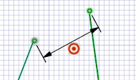
First selection for Parallel:

Second selection for Parallel:

Fixed, Horizontal and Vertical constraints require only one selected drawing object.
The Fixed constraint tool acts as a toggle - click an object to apply, click a second time to remove.
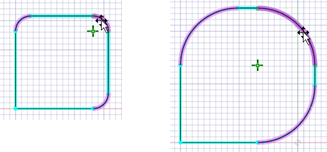
Concentric and Equal Radius constraints propagate when modifying the curves.
The Equal Distance constraint uses on-screen tool guides to determine the anchor and target. See the example below.
Equal Radius constraints are added automatically when you create multiple rounded corners using the Ctrl key and the Create Rounded Corner tool in the Modify group. All the rounds created this way maintain an Equal Radius constraint so that changing the size of one will change all of them.
Adding Dimension Constraints
Activate the Dimension constraint in the Constraints group.
Select an individual sketch object, or two objects as required for certain types of dimensions. Move the cursor away from the object to position the dimension. The normal behavior for applying and locating dimensions is observed. However, when applied as a constraint, if you attempt to edit one object, other objects may be modified to maintain the dimension constraint.
You can use dimension constraints to modify the size of the selected object. After creating the dimension constraint, double-click to select the dimension and then modify the value.
Each dimension is automatically assigned a label. You can also specify labels of your choice.
Note: A valid label should have an alphabet or an underscore (_) as the first character.You can also define dimensions using basic mathematic expressions.
Dimensions may be positioned vertically, horizontally, or aligned with the object.
Angle dimensions are supported - select the first object and then hover over the second object until the angle dimension appears. Move the cursor to position the dimension.
Arc length dimensions are supported - hold the Ctrl key while selecting the arc to create an arc length dimension. Move the cursor to position the dimension.
You can modify the arrow style, expression, label, type of dimension, and precision in the Properties panel.
Adding an Equal Distance Constraint
The Equal Distance constraint uses on-screen tool guides to determine the anchor and target distances, and to create the constraint. This is because more than one selection is often necessary to create the constraint.
Activate the Equal Distance constraint in the Constraints group.
With the Target tool guide active, select your moveable drawing object or pair of geometries to define the first dimension.
A dimension line with the target symbol is added to the design page.
Select the Anchor tool guide (or hold the alt key), and then select your stationary drawing object or pair of geometries.
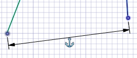
A dimension line with the anchor symbol is added to the design page.
Click the Complete tool guide to create the constraint.
The target object will be modified as required.
Adding Symmetric Constraints
Activate the Symmetric constraint in the Constraints group.
Select the Make ends symmetric option (enabled by default) to make the curve end points symmetric.
With the Select Axis of Symmetry
 tool guide
active, select the axis about which the sketch objects are to be
symmetric.
tool guide
active, select the axis about which the sketch objects are to be
symmetric.With the Select Curves
 tool guide
active, select the pair of curves to be made symmetric. The cursor
symbol changes to indicate whether you are selecting target or
anchor.
tool guide
active, select the pair of curves to be made symmetric. The cursor
symbol changes to indicate whether you are selecting target or
anchor.
The target object will be modified as required.
Adding an Equal Length Constraint
The Equal Length constraint uses on-screen tool guides to determine the anchor and target lengths, and to create the constraint.
Activate the Equal Length constraint in the Constraints group.
With the Target tool guide active, select the target line.
With the Anchor tool guide active, select the source line.
`The target line will be modified accordingly.