


Creating a Dimension Annotation
-
Click the arrow under the
 Dimension tool and select
Dimension.
Dimension tool and select
Dimension.
Dimensioning to and from Center Lines
In a drawing view, add a center line using the
 Center Line tool.
- Click the arrow under the
Dimension tool and select
Dimension.
Click either the horizontal or vertical center line
Click an edge or face.
Click to create the dimension.
Creating an Arc Length Dimension
Two methods:
- Hold the Ctrl key down and click the arc.
- Click the arc first and hold the Ctrl key down while dragging the dimension.
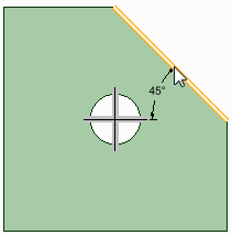
Creating a Chamfer Dimension
Click the arrow under the
Dimension tool and select
Dimension
.If you are creating a dimension in 3D, click a face to create an annotation plane on which to place the dimension.
If you need to change the annotation plane, right-click and click Select New Annotation Plane from the context menu and select a new annotation plane.
Click an edge or face that belongs to the chamfer.
Mouse over your design to preview the possible dimensions.
Click to create the dimension.
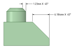
Dimensions for planar and cylindrical chamfers.
You can flip the orientation of chamfer dimensions by setting the Flip Chamfer Dimension property to True.
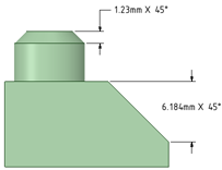
Flipped chamfer dimensions
Annotation options in the General page of Detailing option in DesignSpark Mechanical Options offers choices for how chamfer dimensions are displayed.
-
Default chamfer dimension style:
- Linear: Displays the dimension with extensions lines as in the images above.
-
Normal to chamfer: Displays the dimension with a leader
pointed normal to the chamfer as shown in the image below.
-
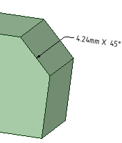
Default chamfer dimension text format:
- <length> X 45: Text is displayed as in the images above.
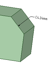
-
C<length>: Text is shown as in the image below.
Creating Ordinate Dimensions
Click the arrow under
Dimension in the Annotation group on the Detailing tab and select
 Ordinate Dimensions.
If you are creating a dimension in 3D, click a face to create the plane on which to place the dimension.
Mouse over the faces of your design to preview the eligible annotation planes. (In Sketch and Section mode, the sketch grid defines the annotation plane.) If multiple objects occur at your cursor location, use the scroll wheel or arrow keys to highlight each one.
To create an annotation plane for a cylindrical face, select the cylinder's axis.
If you need to change the annotation plane, right-click and click Select New Annotation Plane from the context menu. Then right-click the new place and click Set As Annotation Plane.
Click a line, edge, or Center Line to set the baseline dimension.
You can use an existing extension line as a dimensioning reference. An extension line is the line that connects the point to the dimension text. If you select an extension line, the baseline dimension for the extension line's dimension is used.
Mouse over the face to see all the possible dimensions.
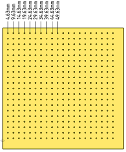
In cases with many ordinate dimensions, the preview may be slow. Start DesignSpark Mechanical using the following command line option to limit the number of dimensions that are shown in the preview. The example specifies '10' but you can set it to any number you wish.
MaxOrdDims=10The plate shown below has 400 holes but only 10 are shown in the preview.
Click a point to place the dimension line.
If you select a face, all of the possible ordinate dimensions will be created.
You can click multiple points to use the same baseline for those dimensions.
The baseline dimension (0) is displayed or hidden based on which detailing standard is selected in the Detailing options.
Automatic jog points are included if ordinate dimensions are too closely spaced. This helps make them easier to read.
Using an Angled Baseline
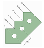
First, establish a simple, oriented dimension. Then use one of the witness lines to set the baseline and orientation of the ordinate dimensions.
In the example above, the leftmost witness line of the existing circle-to-circle dimension was selected to define the baseline.
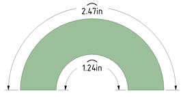
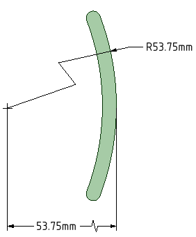
Creating Foreshortened Dimensions
Start with a radius dimension
Optional - Set the Foreshortened radial dimension center size in DesignSpark Mechanical Options
Right-click and select Foreshortened
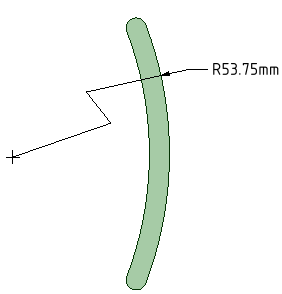
Move the endpoint and jog points as needed.
Dimensioning to the center produces a foreshortened length dimension.
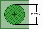
Dimensioning Bodies
Click the arrow under the
Dimension tool and select
Dimension
.Click the Select bodies tool guide on the right side of the Design window.
Select the solid body or bodies you want to dimension:
If you select a single body, then the maximum horizontal or vertical dimension is created, as shown below.
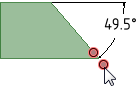
If you select more than one body, then the dimension is created for both solids and is anchored on the side closest to where you click the solid. You must click the Select bodies tool guide before you select each solid, so you click the tool guide and select the first part, then click the tool guide again and select the second part.
In both of the examples below, the upper part was selected near its top. The lower part was selected near its top in the example on the left and near its bottom in the example on the right. The mouse arrows indicate where the lower part was selected. You will see a preview of the dimension when you click the tool guide and hover over the second part.
If you create the dimension in a section view of a drawing sheet, then the dimension is created on the extents of the body that is visible in the section plane, as shown below.
Editing a Dimension Annotation
Select the dimension annotation to move, size, or rotate it.
To move the dimension note, mouse over the edge of the box with the Select tool until the cursor changes to
 , then
drag the note.
, then
drag the note.To size the box that contains the dimension note, drag the handles of the note box (the white circles).
Select the text of the note to reformat it.
(Optional) Right-click the dimension and select text formatting options from the mini-toolbar.
Click
 to
select a tolerance format, then edit the text of the
tolerance.
to
select a tolerance format, then edit the text of the
tolerance.- See the Limits and Fits Tolerances section below for a description of using Limits and Fits.
Click
 to insert a field. You can select a
field type and format from the Insert Field window.
to insert a field. You can select a
field type and format from the Insert Field window.Select from the
 drop-down to insert a symbol.
Click an arrowhead to cycle through alternative leader styles.
You can also right-click an arrowhead and select Arrow Style to select a style for that arrowhead, or select the arrowhead, then select the style for the head in the Properties panel.
Click the note leaders to modify them.
You can right-click a leader and select Add Jog Point to add a new point.
To change the distance between a dimension extension line and its reference point on the object, click the extension line, then hover over the end closest to the object. Drag the red dot to change its distance from the object.
If you cant' see the extension line, hover over the end of the dimension leader, where the line would be. You will see two red dots that you can drag:
Modify the dimension note properties in the Properties panel. Modify the:
Arrow Length and Width properties to set the length and width of the arrowheads
Measurement property to change the measurement type. For example, you may want to display the radius of a hole instead of the diameter.
- Precision property to change the number of decimal places.
Upper Limit, Lower Limit, and Type of tolerance property to change the format of the dimension and enter upper and lower tolerance values.
To fit a dimension within the text box
- Right-click the note and open the Autofit drop-down menu.
Choose one of the following options:
- Do not autofit: The text box adjusts to the size of the text and grows as you type. There is no blank space around the note and making the text larger or smaller adjusts the box accordingly.
- Resize text height on overflow: The text always fits the width of the box. If you make the box wider, text from the second line will move up to the first line.
- Shrink text on overflow: The text adjusts uniformly (width and height) and scales to fit in the text box.
- Shrink text horizontally on overflow: The width of the text changes but the height remains the same.
Limits and Fits Tolerances
Limits and Fits tolerances are supported for Metric units using the ISO 286-1 and ISO 286-2 standards. Refer to these standrads for a complete description of Limits and Fits tolerances.
You can apply Limits and Fits to metric dimensions for Holes, Shafts, and opposing planar faces (that is, face normals point toward each other).
Limits and Fits tolerances are specified with a letter and a number that refer to a table in the standard.