


Applying a Limits and Fits Tolerance
- Select one of the dimensions listed above
- In the Properties panel, change the Tolerance Type to Limits and
Fits, or click
 in the mini toolbar
 Based on the dimension size, the following tolerance properties are set to default values:
- Upper Limit - The largest allowable value for the dimension
- Lower Limit - The smallest allowable value for the dimension
- System of Fits - Sets the fixed datum used to calculate the tolerances. This can be either Hole Basis (shaft is assembled into the hole) or Shaft Basis (hole is assembled onto the shaft).
- Hole Fundamental Deviation - Fundamental Deviation establishes the location of the tolerance zone with respect to the Basic Size. When System of Fits is set to Hole Basis, this will be "H". When System of Fits is set to Shaft Basis, this can be any of the allowed letter designations (A thru ZC)
- Hole IT - "IT" refers to International Tolerance Grade. It is a group of tolerances which vary depending on the Basic Size of the dimension, but which provide the same relative accuracy within a given grade .Any of the allowed numeric designations (IT01 thru IT18)
- Shaft Fundamental Deviation - Fundamental Deviation establishes the location of the tolerance zone with respect to the Basic Size. When System of Fits is set to Hole Basis, this will be any of the allowed letter designations (a thru zc). When System of Fits is set to Shaft Basis, this will be "h".
- Shaft IT - Any of the allowed numeric designations (IT01 thru IT18)
- Method of Designating - The display format for the tolerance
- Change any of the properties as appropriate
In the Limits and Fits section of DesignSpark Mechanical Options > Detailing, you can set defaults for the properties.
Limits and Fits symbols combine the IT Grade Number and the Fundamental Deviation letter. "IT" is dropped from the Grade Number so only the number is shown. The tolerance size is therefore defined by the Basic Size of the part followed by a symbol containing a letter and a number. A Fit is indicated by the Basic Dimension common to both components, followed by a symbol corresponding to both components with the Internal part symbol preceding the External part symbol.
The table below shows examples.
| Internal (hole) component |  |
| External (shaft) component | 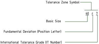 |
| Fit between a hole and shaft with a basic size of 40 | 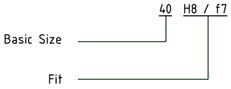 |
Set the Method of Designating property to change the symbol's display format. The table below illustrates the choices.
| 40H8 | 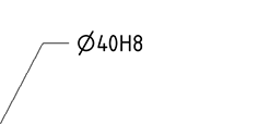 |
| 40H8 (40.039/40) | 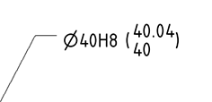 |
| 40.039/40 (40H8) | 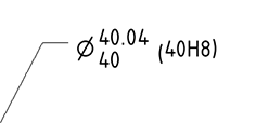 |
| 40.039/40 | 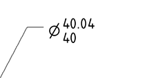 |
| 40H8/h7 | 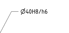 |
When you change the size of a dimension that has Limits and Fits tolerances, the Upper and Lower Limits will change according to the limits and Fits tolerance tables.
If you modify the IT number, the tolerance symbol updates accordingly.
The dimension color is changed to Red if it has Limits and Fits tolerance and some of the input parameters are invalid. An example is shown below.
| The tolerance has a Fit for H01/n01 |  |
| The Fit was changed to H01/a01, which is invalid | 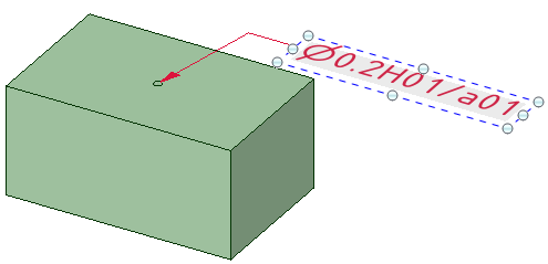 |
Displaying the Annotation and Hiding the Plane
Create two layers, one for notes, and one for the annotation planes.
Place the note on one layer and the annotation plane on another layer.
Turn off the visibility of the layer that contains the annotation plane.
Aligning Multiple Dimensions
- Select multiple dimensions.
In the RMB menu, choose from the following:
- Align Lefts - Align the left side of each dimension.
- Align Centers - Vertically align the center of each dimension.
- Align Rights - Align the right side of each dimension.
- Align Top Lines - Align the bottom of the first line of text in each dimension.
- Align Middles - Horizontally align the middle of each dimension.
- Align Bottom Lines - Align the bottom of the last line of text in each dimension.
- Make Same width - Make each dimension the same width based on the first note selected. Some text may be scaled accordingly.
- Make Same Height - Make each dimension the same height based on the first note selected. Some text may be scaled accordingly.
- Make Same Size - Make each dimension the same size (height and width) based on the first note selected. Some text may be scaled accordingly.
- Distribute Horizontally - The space between each dimension is distributed evenly horizontally.
- Distribute Vertically -The space between each dimension is distributed evenly vertically.
- Remove Horizontal Spacing - The even horizontal spacing is removed and any significant overlap is equalized.
- Remove Vertical Spacing - The even vertical spacing is removed and any significant overlap is equalized.
Any notes rotated differently are not affected by the above commands.
Displaying Dimensions for an Annotation Plane
Right-click an annotation plane and select:
- Show all dimensions to display dimensions on all annotation planes.
- Show dimensions to display the dimensions for only the annotation plane you right-clicked.