


Associating the Blocking to Geometry
The Associate
![]() tool
creates logical links between the blocking topology (faces, edges, vertices) and CAD
geometry (surfaces, curves, points). This allows the blocking, and therefore the mesh, to
be updated automatically when the geometry is modified. It also allows blocking topology to
be reused with similar geometry. When a blocking file is loaded, the software will attempt
to re-associate the blocking topology to the nearest appropriate geometry.
tool
creates logical links between the blocking topology (faces, edges, vertices) and CAD
geometry (surfaces, curves, points). This allows the blocking, and therefore the mesh, to
be updated automatically when the geometry is modified. It also allows blocking topology to
be reused with similar geometry. When a blocking file is loaded, the software will attempt
to re-associate the blocking topology to the nearest appropriate geometry.
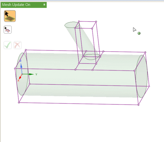
Blocking entities may be associated with geometry entities of the same or higher dimension. That is, blocking vertices (0D) may be associated with geometry points (0D), curves (1D), or surfaces (2D); but blocking faces (2D) may be associated only with geometry surfaces. Such associations will constrain independent movement of blocking entities.
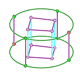
Visually, the existence of associations changes the colors of the blocking entities. In this image,
- Red vertices are associated to points on the geometry. If you attempt to move these without first disassociating, the geometry may also be modified.
- Green vertices and edges are associated to curves on the geometry. You may move the vertices but they will be constrained to stay on the associated curve.
- Purple (pink) vertices and edges are associated to surfaces. You may move the vertices, but they will be constrained to stay on the associated surface.
- Blue (cyan) vertices and edges are not associated to any geometry. You may move the vertices freely.
When block edges are associated to curves, you can project the edge shape to match the geometry or identify the associated curve.
- To project the edge shape, go to the Mesh Display panel. Under Block display options, enable Projected Shape. The blocking edge will follow any geometry curvature.
- To identify the associated curve, disable Projected Shape and select the blocking edge(s) using the Associate tool. Small arrows will appear between the selected edge(s) and associated curve(s).