


Setting Blocking Options
| Enable Advanced Tools |
[Optional] Use the check box to disable or Enable Advanced Tools. Default and general recommendation are to enable Advanced Tools. If you disable Advanced Tools, the block editing tools (Edit group on the Mesh ribbon) and the blocking topology will be hidden. |
|
| Automatic Multi-Threaded Block Meshing |
[Optional] Use the check box to enable or disable Automatic Multi-Threaded Block Meshing. By default, SpaceClaim Meshing will use multi-thread processing when creating the mesh. For example, multiple surfaces meshed in parallel will be processed in multiple threads. You can allow the software to select the number of threads automatically, or manually set the maximum number of threads. Note: This affects only the number of
threads for mesh processing. SpaceClaim will use additional threads
for other processes such as Progress bar updates.
|
|
| Max # Elements Display Limit |
Specifies the limit for the maximum number of elements displayed for the blocking mesh quality. If the model comprises more elements than the number specified, the blocking mesh quality and properties may not be computed completely. In such cases, you may increase the limit for maximum number of elements to view the computed quality. |
|
| Normal projection instead of closest |
[Optional] Use the check box to enable Normal projection instead of closest. By default, this option is disabled, that is, blocking entities are projected to the closest point on the geometry. When this option is enabled, blocking entities are projected normal to the geometry. |
|
| Project inner faces when they become (material) boundaries |
[Optional] Use the check box to enable Project inner faces when they become (material) boundaries. By default, this option is disabled. When this option is enabled, block associations are modified while splitting or deleting blocks, or changing block material. Inner block faces that are changed to boundary faces are projected to the geometry. You may use the Associate tool to remove the association, if required. |
|
| Prime surface meshing |
[Optional] Use the check box to enable Prime surface meshing. By default, this option is disabled. When this option is enabled, an alternative surface meshing method is used for faster surface meshing performance for models having large surfaces with many cut out loops. Note that the surface mesh quality may deteriorate when this method is used. |
|
| Use Split Angle |
[Optional] Use the check box to enable Use Split Angle to split edges to improve the mapped mesh quality and prevent skewed mesh on side faces. This option is disabled by default. In cases where the mesh is skewed, you can enable this option to create new splits rather than align to existing splits. Specify an appropriate value for the split angle (default 60 degrees). Splits will be created at nodes where the angle of an end node of an edge (edge vector) to the corresponding end node of a parallel edge is less than the split angle specified. The examples show the improved mesh quality using this option. |
|
Original Mesh - before using the Split Angle 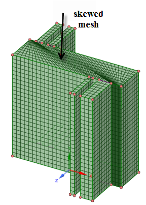 |
Improved mesh - after using the Split Angle 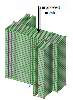 |
|
| Project to Bspline |
Use this option to project the mesh to the true Bspline geometry rather than the faceted representation, which is the internal triangulated representation of surface data. This can be used instead of decreasing the triangulation tolerance or using the projection limit, where small gaps in the faceted representation can create skewed mesh elements. This, however, takes longer and more memory to compute the mesh.
|
|
| Projection Limit |
Use this option to control the projection of nodes. The Projection limit is set to a non-zero value in cases where you want to keep the nodes on the edges and avoid projection to the underlying surfaces. This option is typically used when the mesh spacing is small relative to the geometry tolerance. Allowing nodes within a gap in the geometry to project would result in skewed mesh elements. With a value P set to slightly larger than the gap, the nodes would instead be interpolated.
|
|
| Use Triangulation Tolerance |
[Optional] Use this option to set a user-defined relative triangulation tolerance for the geometry import. The triangulation tolerance is the distance allowed between the triangle edge and the actual surface edges. A lower tolerance will give a good representation of the geometry but will require more memory and longer processing time, while a higher tolerance will give good performance and less memory usage but a coarser representation of the geometry. An optimal value for most models is 0.001. This setting is independent of the mesh element size. Note: The triangulation tolerance does not
affect faceted geometry.
|
|