| DesignSpark Mechanical Online Help |
|
Use the Dimension Annotation on a drawing showing measurement of an edge or face. Use the Dimension tool to add
measurements to your design, drawing sheet, or 3D markup. tool to add a measurement to your design or drawing sheet.
Annotation on a drawing showing measurement of an edge or face. Use the Dimension tool to add
measurements to your design, drawing sheet, or 3D markup. tool to add a measurement to your design or drawing sheet.
You can use annotation dimensions with the PullTool used to distort or deform geometry. Use the Pull tool to offset, extrude, revolve, sweep,
draft, and blend faces; or to round, chamfer, or extrude edges. When converting a sketch to 3D, pulling a
line creates a surface and pulling a surface creates a solid. and MoveA tool used to translate or rotate geometry. tools to change your design. See Driving modifications with annotation dimensions.
An annotation plane cannot be moved to a sub-component after you add dimensions because the references would be lost.
You can enable dual dimensions, which will display each dimension in both Metric and Imperial units. See Units options.

Click ![]() DimensionAnnotation on a drawing showing measurement of an edge or face. Use the Dimension tool to add
measurements to your design, drawing sheet, or 3D markup. tool Annotation on a drawing showing measurement of an edge or face. Use the Dimension tool to add
measurements to your design, drawing sheet, or 3D markup.
DimensionAnnotation on a drawing showing measurement of an edge or face. Use the Dimension tool to add
measurements to your design, drawing sheet, or 3D markup. tool Annotation on a drawing showing measurement of an edge or face. Use the Dimension tool to add
measurements to your design, drawing sheet, or 3D markup.
If you are creating a dimension in 3D, click a face to create an annotation plane on which to place the dimension.
Mouse over the faces of your design to preview the eligible annotation planes. (In Sketch and Section modeSee SectionDesign2D or 3D model that contains at least one top-level component. mode in which you edit solids by working with their edges and vertices in cross-section. ViewOrientation settings that you can apply to your design, including spin, pan, and zoom. You can adjust
these settings individually or you can apply one of the following preconfigured views: Trimetric, Isometric,
Top, Bottom, Front, Back, Right, Left. You can also select Snap View and click a face to view it head-on. is
cut away to show interior detail., the sketch grid defines the annotation plane.) If multiple objects occur at your cursor location, use the scroll wheel or arrow keys to highlight each one.
To create an annotation plane for a cylindrical face, select the cylinder's axis.
If you need to change the annotation plane, right-click and click Select New AnnotationInformation you can add to a drawing, such as notes, dimensions, geometric tolerances,
center marks, and Bills of Materials. PlaneConstruction geometry consisting of a flat surface. Planes can be used for a 2D sketch, section
view of a model, a neutral plane in a draft feature. from the context menu and select a new annotation plane.
Click an edge or face.
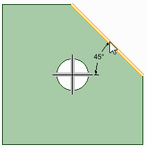
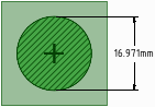
Where you click on a circle determines whether you will measure from the circle's center, near, or far edge. To select the center click the top, bottom, left, or right side of the circle.
Mouse over your design to preview the possible dimensions.
Click a second object if you want to dimension between two objects.
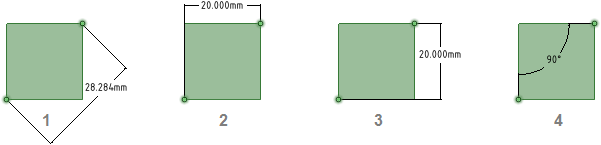
(Optional) Select a dimension orientation in the Options panelArea of the user interface that enables you to modify functions specific to tools.. You can also select the orientation for the first and second reference.
Click to create the dimension.
In a drawing view, add a center line using the  Center LineA straight line, arc, or spline drawn in Sketch mode or on a layout plane. Lines have length but no area.
When you pull a sketch into 3D with the PullTool used to distort or deform geometry. Use the Pull tool to offset, extrude, revolve, sweep,
draft, and blend faces; or to round, chamfer, or extrude edges. When converting a sketch to 3D, pulling a
line creates a surface and pulling a surface creates a solid. tool, lines become edges. tool.
Center LineA straight line, arc, or spline drawn in Sketch mode or on a layout plane. Lines have length but no area.
When you pull a sketch into 3D with the PullTool used to distort or deform geometry. Use the Pull tool to offset, extrude, revolve, sweep,
draft, and blend faces; or to round, chamfer, or extrude edges. When converting a sketch to 3D, pulling a
line creates a surface and pulling a surface creates a solid. tool, lines become edges. tool.
Annotation on a drawing showing measurement of an edge or face. Use the Dimension tool to add
measurements to your design, drawing sheet, or 3D markup. tool Annotation on a drawing showing measurement of an edge or face. Use the Dimension tool to add
measurements to your design, drawing sheet, or 3D markup.Click either the horizontal or vertical center line
Click an edge or face.
Click to create the dimension.
Two methods:
Click ![]() DimensionAnnotation on a drawing showing measurement of an edge or face. Use the Dimension tool to add
measurements to your design, drawing sheet, or 3D markup. tool Annotation on a drawing showing measurement of an edge or face. Use the Dimension tool to add
measurements to your design, drawing sheet, or 3D markup.
DimensionAnnotation on a drawing showing measurement of an edge or face. Use the Dimension tool to add
measurements to your design, drawing sheet, or 3D markup. tool Annotation on a drawing showing measurement of an edge or face. Use the Dimension tool to add
measurements to your design, drawing sheet, or 3D markup.
If you are creating a dimension in 3D, click a face to create an annotation plane on which to place the dimension.
If you need to change the annotation plane, right-click and click Select New AnnotationInformation you can add to a drawing, such as notes, dimensions, geometric tolerances,
center marks, and Bills of Materials. PlaneConstruction geometry consisting of a flat surface. Planes can be used for a 2D sketch, section
view of a model, a neutral plane in a draft feature. from the context menu and select a new annotation plane.
Click an edge or face that belongs to the chamfer.
Mouse over your design to preview the possible dimensions.
Click to create the dimension.
DimensionsValues or expressions you enter for precise control during the creation or modification of a design.
You can dimension every element, from lines in sketches to faces of solids. See Ordinate dimensions, Progressive dimensions,
Ruler dimension. for planar and cylindrical chamfers.
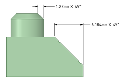
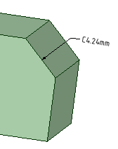
You can flip the orientation of chamfer dimensions by setting the Flip ChamferSloping corner between two edges created using the PullTool used to distort or deform geometry. Use the Pull tool to offset, extrude, revolve, sweep,
draft, and blend faces; or to round, chamfer, or extrude edges. When converting a sketch to 3D, pulling a
line creates a surface and pulling a surface creates a solid. tool; angle with equal setback; bevel. DimensionAnnotation on a drawing showing measurement of an edge or face. Use the Dimension tool to add
measurements to your design, drawing sheet, or 3D markup. property to True.
Flipped chamfer dimensions
AnnotationInformation you can add to a drawing, such as notes, dimensions, geometric tolerances,
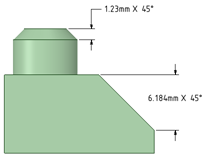
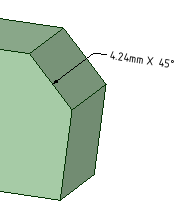
center marks, and Bills of Materials. options in the General page of Detailing option in DS Mechanical Options offers choices for how chamfer dimensions are displayed.
The vector that is perpendicular to a flat plane at the selected point. In the case of a non-flat
plane, the vector that is perpendicular to the plane tangent to the surface at the selected point. to chamfer: Displays the dimension with a leader pointed normal to the chamfer as shown in the image below.
Click the arrow under ![]() DimensionAnnotation on a drawing showing measurement of an edge or face. Use the Dimension tool to add
measurements to your design, drawing sheet, or 3D markup. in the AnnotationInformation you can add to a drawing, such as notes, dimensions, geometric tolerances,
center marks, and Bills of Materials. group on the Detailing tab and select
DimensionAnnotation on a drawing showing measurement of an edge or face. Use the Dimension tool to add
measurements to your design, drawing sheet, or 3D markup. in the AnnotationInformation you can add to a drawing, such as notes, dimensions, geometric tolerances,
center marks, and Bills of Materials. group on the Detailing tab and select ![]() Ordinate DimensionsValues or expressions you enter for precise control during the creation or modification of a design.
You can dimension every element, from lines in sketches to faces of solids. See Ordinate dimensions, Progressive dimensions,
Ruler dimension..
Ordinate DimensionsValues or expressions you enter for precise control during the creation or modification of a design.
You can dimension every element, from lines in sketches to faces of solids. See Ordinate dimensions, Progressive dimensions,
Ruler dimension..
If you are creating a dimension in 3D, click a face to create the plane on which to place the dimension.
Mouse over the faces of your design to preview the eligible annotation planes. (In Sketch and Section modeSee SectionDesign2D or 3D model that contains at least one top-level component. mode in which you edit solids by working with their edges and vertices in cross-section. ViewOrientation settings that you can apply to your design, including spin, pan, and zoom. You can adjust
these settings individually or you can apply one of the following preconfigured views: Trimetric, Isometric,
Top, Bottom, Front, Back, Right, Left. You can also select Snap View and click a face to view it head-on. is
cut away to show interior detail., the sketch grid defines the annotation plane.) If multiple objects occur at your cursor location, use the scroll wheel or arrow keys to highlight each one.
To create an annotation plane for a cylindrical face, select the cylinder's axis.
If you need to change the annotation plane, right-click and click Select New AnnotationInformation you can add to a drawing, such as notes, dimensions, geometric tolerances,
center marks, and Bills of Materials. PlaneConstruction geometry consisting of a flat surface. Planes can be used for a 2D sketch, section
view of a model, a neutral plane in a draft feature. from the context menu. Then right-click the new place and click Set As AnnotationInformation you can add to a drawing, such as notes, dimensions, geometric tolerances,
center marks, and Bills of Materials. PlaneConstruction geometry consisting of a flat surface. Planes can be used for a 2D sketch, section
view of a model, a neutral plane in a draft feature..
Click a line, edge, or Center LineA straight line, arc, or spline drawn in Sketch mode or on a layout plane. Lines have length but no area.
When you pull a sketch into 3D with the PullTool used to distort or deform geometry. Use the Pull tool to offset, extrude, revolve, sweep,
draft, and blend faces; or to round, chamfer, or extrude edges. When converting a sketch to 3D, pulling a
line creates a surface and pulling a surface creates a solid. tool, lines become edges. to set the baseline dimension.
You can use an existing extension line as a dimensioning reference. An extension line is the line that connects the point to the dimension text. If you select an extension line, the baseline dimension for the extension line's dimension is used.
Mouse over the face to see all the possible dimensions.
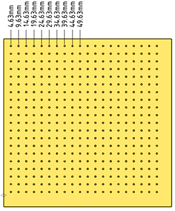
In cases with many ordinate dimensions, the preview may be slow. Start DS Mechanical using the following command line option to limit the number of dimensions that are shown in the preview. The example specifies '10' but you can set it to any number you wish.
MaxOrdDims=10
The plate shown below has 400 holes but only 10 are shown in the preview.
Click a point to place the dimension line.
If you select a face, all of the possible ordinate dimensions will be created.
You can click multiple points to use the same baseline for those dimensions.
The baseline dimension (0) is displayed or hidden based on which detailing standard is selected in the Detailing options.
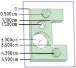
Automatic jog points are included if ordinate dimensions are too closely spaced. This helps make them easier to read.
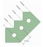
First, establish a simple, oriented dimension. Then use one of the witness lines to set the baseline and orientation of the ordinate dimensions.
In the example above, the leftmost witness line of the existing circle-to-circle dimension was selected to define the baseline.
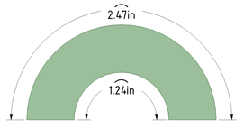
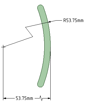
Start with a radius dimension
Optional - Set the Foreshortened radial dimension center size in DS Mechanical Options
Right click and select Foreshortened
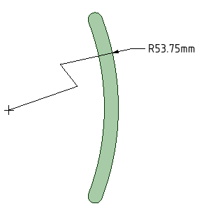
MoveA tool used to translate or rotate geometry. the endpoint and jog points as needed.
Dimensioning to the center produces a foreshortened length dimension.
Click ![]() DimensionAnnotation on a drawing showing measurement of an edge or face. Use the Dimension tool to add
measurements to your design, drawing sheet, or 3D markup. tool Annotation on a drawing showing measurement of an edge or face. Use the Dimension tool to add
measurements to your design, drawing sheet, or 3D markup.
DimensionAnnotation on a drawing showing measurement of an edge or face. Use the Dimension tool to add
measurements to your design, drawing sheet, or 3D markup. tool Annotation on a drawing showing measurement of an edge or face. Use the Dimension tool to add
measurements to your design, drawing sheet, or 3D markup.
Click the Select bodies tool guide on the right side of the Design windowArea in the user interface that displays your model or assembly. Also known as Workspace..
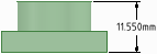
Select the solid body or bodies you want to dimension:
If you select a single body, then the maximum horizontal or vertical dimension is created, as shown below.
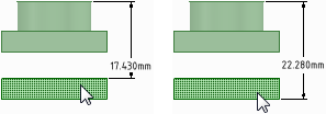
If you select more than one body, then the dimension is created for both solids and is anchored on the side closest to where you click on the solid. You must click on the Select bodies tool guide before you select each solid, so you click the tool guide and select the first part, then click the tool guide again and select the second part.
In both of the examples below, the upper part was selected near its top. The lower part was selected near its top in the example on the left and near its bottom in the example on the right. The mouse arrows indicate where the lower part was selected. You will see a preview of the dimension when you click the tool guide and hover over the second part.
If you create the dimension in a section view of a drawing sheet, then the dimension is created on the extents of the body that is visible in the section plane, as shown below.
Select the dimension annotation to move, size, or rotate it.
To move the dimension note, mouse over the edge of the box with the Select tool until the cursor changes to ![]() , then drag the note.
, then drag the note.
To size the box that contains the dimension note, drag the handles of the note box (the white circles).
Select the text of the note to reformat it.
(Optional) Right-click the dimension and select text formatting options from the mini-toolbar.
Click ![]() to select a tolerance format, then edit the text of the tolerance.
to select a tolerance format, then edit the text of the tolerance.
Click ![]() to insert a field. You can select a field type and format from the Insert Field window.
to insert a field. You can select a field type and format from the Insert Field window.
Select from the ![]() drop-down to insert a symbol.
drop-down to insert a symbol.
Click an arrowhead to cycle through alternative leader styles.
You can also right-click an arrowhead and select Arrow Style to select a style for that arrowhead, or select the arrowhead, then select the style for the head in the Properties panelArea of the user interface that displays editable details about the selected object(s). This panel is initially displayed on the lower left side of the screen, but can be moved..
Click the note leaders to modify them.
You can right-click a leader and select Add Jog PointSingle location in the sketch grid. 2-D object that has no height, width, or length. The origin,
an axis, and a vertex are examples of points. Use the Point tool to sketch a point on the sketch grid. Points
are useful as a dimensional reference, for splitting, and for creating a point on a line or curve through which
you want to draw a three-point circle. to add a new point.
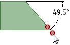
To change the distance between a dimension extension line and its reference point on the object, click on the extension line, then hover over the end closest to the object. Drag the red dot to change its distance from the object.
If you cant' see the extension line, hover over the end of the dimension leader, where the line would be. You will see two red dots that you can drag:
Modify the dimension note properties in the Properties panelArea of the user interface that displays editable details about the selected object(s). This panel is initially displayed on the lower left side of the screen, but can be moved.. Modify the:
Arrow Length and Width properties to set the length and width of the arrowheads
Measurement property to change the measurement type. For example, you may want to display the radius of a hole instead of the diameter.
Upper Limit, Lower Limit, and Type of tolerance property to change the format of the dimension and enter upper and lower tolerance values.
Limits and Fits tolerances are supported for Metric units using the ISOInternational Organization for Standardization standards for architectural and engineering drawing,
including guidelines for dimensioning and tolerancing. You can customize the style of your annotations
to conform to ISO standards. See ASME, JISJapanese Standards Association standards for technical drawings. You can customize the style of your
annotations to conform to JIS standards. JIS defaults are the same as ISO, except that JIS uses third-angle
views while ISO uses first-angle views. See ASME, ISO.. 286-1 and ISOInternational Organization for Standardization standards for architectural and engineering drawing,
including guidelines for dimensioning and tolerancing. You can customize the style of your annotations
to conform to ISO standards. See ASME, JISJapanese Standards Association standards for technical drawings. You can customize the style of your
annotations to conform to JIS standards. JIS defaults are the same as ISO, except that JIS uses third-angle
views while ISO uses first-angle views. See ASME, ISO.. 286-2 standards. Refer to these standrads for a complete description of Limits and Fits tolerances.
You can apply Limits and Fits to metric dimensions for Holes, Shafts, and opposing planar faces (i.e. face normals point toward each other).

|
If the dimension is created by selecting an edge, the Limits and Fits tolerance type will be available ONLY IF the system can uniquely determine the parent faces. If there is ambiguity, Limits and Fits may not be available as a tolerance type. |
|
|
Limits and Fits will NOT be available if the dimension (i.e. Basic Size) is outside the range of sizes covered by the standard. |
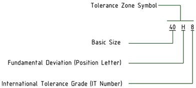
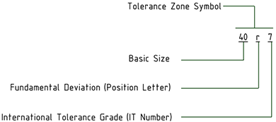
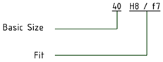
Limits and Fits tolerances are specified with a letter and a number that refer to a table in the standard.
Area of the user interface that displays editable details about the selected object(s). This panel is initially displayed on the lower left side of the screen, but can be moved., change the Tolerance Type to Limits and Fits, or click In the Limits and Fits section of DS Mechanical Options > Detailing, you can set defaults for the properties.
Limits and Fits symbols combine the IT Grade Number and the Fundamental Deviation letter. "IT" is dropped from the Grade Number so only the number is shown. The tolerance size is thus defined by the Basic Size of the part followed by a symbol containing a letter and a number. A Fit is indicated by the Basic DimensionAnnotation on a drawing showing measurement of an edge or face. Use the Dimension tool to add
measurements to your design, drawing sheet, or 3D markup. common to both components, followed by a symbol corresponding to both components with the Internal part symbol preceding the External part symbol.
The table below shows examples.
| Internal (hole) component |
|
| External (shaft) component |
|
| Fit between a hole and shaft with a basic size of 40 |
|
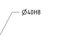
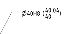
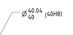
Set the Method of Designating property to change the symbol's display format. The table below illustrates the choices.
| 40H8 |
|
| 40H8 (40.039/40) |
|
| 40.039/40 (40H8) |
|
| 40.039/40 |
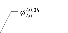
|
| 40H8/h7 |
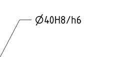
|
When you change the size of a dimension that has Limits and Fits tolerances, the Upper and Lower Limits will change according to the limits and Fits tolerance tables.
If you modify the IT number, the tolerance symbol updates accordingly.
The dimension color is changed to Red if it has Limits and Fits tolerance and some of the input parameters are invalid. An example is shown below.
| The tolerance has a Fit for H01/n01 |
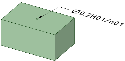
|
| The Fit was changed to H01/a01, which is invalid |
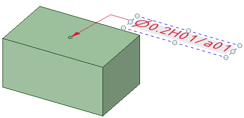
|
Create two layers, one for notes, and one for the annotation planes.
Place the note on one layer and the annotation plane on another layer.
Turn off the visibility of the layer that contains the annotation plane.
Any notes rotated differently are not affected by the above commands.
Right-click an annotation plane and select:
Annotations with orientation changed in the Options panelArea of the user interface that enables you to modify functions specific to tools.
DimensionAnnotation on a drawing showing measurement of an edge or face. Use the Dimension tool to add
measurements to your design, drawing sheet, or 3D markup. Orientation set to Aligned
DimensionAnnotation on a drawing showing measurement of an edge or face. Use the Dimension tool to add
measurements to your design, drawing sheet, or 3D markup. Orientation set to Horizontal
DimensionAnnotation on a drawing showing measurement of an edge or face. Use the Dimension tool to add
measurements to your design, drawing sheet, or 3D markup. Orientation set to Vertical
1st Reference Orientation set to Horizontal, 2nd Reference Orientation set to Vertical
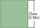
A dimension annotation with dual dimensions enabled in the Units options
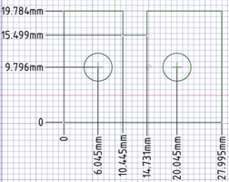
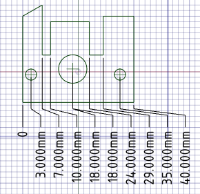
Ordinate dimension annotations
Ordinate dimensionsX or Y distances that originate from a single location, which is usually the lower left corner of
the object. Also known as datum dimensioning or baseline dimensioning for a planar face
Automatic jog points with closely spaced ordinate dimensions
© Copyright 2020 Allied Electronics, Inc. All rights reserved.
 Dimensioning to and from center lines