- Copyright and Trademark Information
- File Operations
- Creating, Opening, and Saving Documents
- Creating a New Design
- Creating a New Drawing Sheet for the Active Design
- Creating a New Design and Associated Drawing Sheet
- Opening an Existing Design or Drawing Sheet
- Opening an Existing Design by Dragging and Dropping
- Inserting a Design by Dragging and Dropping
- Saving a Design
- Saving a Design and Using It as a Template
- Copying a Design
- Archiving a Design
- Sending a Design
- Saving a Version of Your Design
- Saving a Design as Another File Type
- Closing a Design
- Modifying Design Properties
- Adding Custom Properties
- Importing and Exporting
- Importing a Design
- Exporting a Design
- Importing: Supported File Types
- Exporting: Supported File Formats
- Importing a Design by Dragging and Dropping
- Exporting a Design as an Image
- Copying the Contents of the Design Window to Windows Clipboard
- Opening the Parent Document of a Design
- Converter Utility
- Running the Converter
- Copying and Pasting from Other Applications
- Locking and Unlocking Objects
- Printing Drawing Sheets and Designs
- DesignSpark Mechanical File Format
- Creating, Opening, and Saving Documents
- Introduction
- User's Guide
- Getting Started Using DesignSpark Mechanical
- Quick Reference Card
- Mouse and Touch Gestures
- The DesignSpark Mechanical Interface
- DesignSpark Mechanical Objects
- Working with Components
- Creating a Component
- Activating a Component
- Cutting, Copying and Pasting a Component
- Mirroring a Component
- Sorting Objects within a Component
- Renaming a Component
- Deleting a Component
- Flattening Assemblies
- Internal, External, and Independent Components
- Internal Components
- External Components
- Dependent and Independent Components
- Notes About Dependent and Independent Components
- Examples
- Inserting a Component or Assembly
- Making a Component Independent
- Making an Internal Component External
- Making a Copy of an External Component Internal
- Saving a Copy of an External Component
- Lightweight Components
- Working with Faceted Bodies
- Working with Components
- Undo and Redo
- Selecting
- Select Tool and Modes
- Using the Select Tool
- Using the Selection Context Menu
- Clearing a Selection
- Reverting Your Selection
- Selecting by Rolling the Mouse Wheel
- Select Tool Guide
- Clip with Plane Tool
- Clip with Volume Tool
- Filtering the Selection
- Using Box Mode
- Using Lasso Mode
- Using Polygon Mode
- Using Paint Mode
- Using Boundary Mode
- Select Components Mode
- Designing
- Cutting, Copying, and Pasting
- Sketching
- Locking a Base Point
- Changing the Location of a Base Point
- Editing a Sketch
- Toggling Between a Curve and a Construction Curve
- Mirroring in Sketch Mode
- Sketch Ribbon
- Sketch Tool Guide
- Sketch Mini-toolbar
- Sketch Tool Options
- The Sketch Plane
- Move Grid Tool
- Sketch Options
- Sketching with Constraints
- Sketch Tools
- Line Tool
- Rectangle Tool
- Ellipse Tool
- Circle Tool
- Arcs
- Polygon Tool
- Splines
- Point Tool
- Trimming and Modifying
- Face Curve Tool
- Project to Sketch Tool
- Equation Tool
- Working with Sketch Curves in 3D
- Editing Sketches
- Copying a Sketch
- Layout Sketches
- Moving in Two Dimensions
- Dimensional Sketching
- Design Modes
- Editing
- Edit Ribbon Group
- Pulling with the Pull Tool
- Creating and Editing a Solid
- Pull Tool Guides
- Pull Tool Options
- Pull Tool Examples
- Offsetting or Extruding Faces
- Extending or Extruding Surface Edges
- Rounding Edges
- Rounding Between Faces and Surfaces
- Modifying Rounds
- Chamfering Edges
- Extruding Edges
- Pivoting Edges
- Revolving Faces
- Revolving Edges
- Revolving Helices
- Sweeping
- Drafting Faces
- Creating Slots
- Scaling Solids and Surfaces
- Copying Edges and Faces
- Pulling with the Select tool
- Pivoting an Edge with the Select Tool
- Using Measure to Drive Pull
- Move Tool
- Fill Tool
- Blend Tool
- Editing with Annotation Dimensions
- Mathematical Expressions
- Intersecting
- Intersect Ribbon Group
- Combine and Split Tools
- Splitting Solids and Surfaces
- Merging Solids and Surfaces
- Making 3D Curves at the Intersection Between Faces
- Combine Tool Guides
- Combine Options
- Combine Examples
- Using Combine to Merge Solids and Surfaces
- Merging Solids
- Merging Surfaces
- Merging Surface Protrusions
- Capping a Surface with a Plane
- Removing Material From a Solid
- Splitting Bodies and Surfaces
- Splitting a Surface
- Splitting a Solid with a Surface, Plane, or Another Solid
- Split Body Tool
- Splitting Faces or Edges
- Project Tool
- Datum Objects and Relationships
- Bodies
- Dimensions
- Detach
- Checking Geometry
- Changing the Display
- Orienting Designs
- Styles
- Applying Colors
- Line Styles
- Layers Panel
- Applying a Graphics Style
- Applying a Rendering Style
- Displaying Edges
- Painting Display Properties with Style Painter
- Flythrough
- Workspace Windows
- Sketch Grid Styles
- Displaying Workspace Tools
- Showing and Hiding Objects
- Displaying Lightweight Components
- Detailing
- General Detailing Options
- Drawing Sheet Size and Format Options
- Modular Grid Options
- Formatting Note Text
- Annotation
- Annotation Ribbon Group
- Dimension Tool
- Note Tool
- Creating a Note
- Creating a Note Field
- Copying a Note
- Editing a Note
- Fitting Text Within a Note Box
- Adjusting the Text Width
- Adjusting Line and Character Spacing
- Aligning Multiple Notes
- Attaching and Detaching Notes to Other Notes
- Attaching and Detaching Free Notes to Drawing Views
- Displaying the Text of an Annotation and Hiding the Plane
- Creating Circular Notes
- Adding Hyperlinks to Annotations
- Note Leader Tool
- Thread Tool
- Center Marks and Lines
- Geometric Dimensioning and Tolerancing
- Encoding Geometric Tolerances
- ASME and ISO Standards
- What You Need to Encode a GD&T Symbol
- Encoding a GD&T Symbol
- Modifiers
- Multi-Segment Feature Control Frame
- Feature-Relating Tolerance Zone Framework
- Datum Features Symbols for Patterns
- Datum Reference Frame
- Datum Targets
- Datum Targets as Datum Features
- Basic Dimensions
- Creating Symbols from Items in the Tree
- Locking Encoded Features
- Track Encoding
- Track Encoding Example
- Geometric Tolerance Tool
- Datum Symbol Tool
- Datum Target Tool
- Encoding Geometric Tolerances
- Welding Symbols
- Barcode Tool
- Bolt Circle Tool
- Bill of Materials (BOMs) Tool
- Balloon Tool
- Surface Finish Symbols
- Table Tool
- Hole Tables
- Curve Table Tool
- Drawing Sheet Views
- Custom Symbols
- Drawing Sheets
- Measuring and Analyzing
- Customizing DesignSpark Mechanical
- Option Types
- Popular Options
- General Detailing Options
- Drawing Sheet Size and Format Options
- Modular Grid Options
- Limits and Fits Options
- Appearance Options
- Selection Options
- Snap Options
- Units Options
- Navigation Options
- Advanced Options
- File Import and Export Options
- Support File Options
- Quick Access Toolbar Options
- Multitouch Options
- Displaying Workspace Tools
- Configuring Windows
- Customizing a View
- Creating Custom Shortcuts
- Getting Help
- Glossary
Creating a Flag Group From a Dimension Annotation
Flag groups capture measurements and ensure that unwanted changes are NOT made to the model.
Flag Group Example
This example steps through the Flag Group functionality using a simple block.
The right face area is added to a Flag Group. | ![]() |
Modifications to the model that do NOT change the right face area can be made as usual. | ![]() |
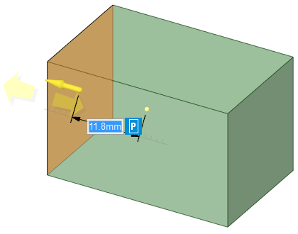
Here a Pull operation is performed that changes the right face area. | ![]() |
Because of the Flag Group, the model snaps back with a warning message. | |
You can unlock a Flag Group by right-clicking on it in the Groups panel and choosing
Unlock. After it is unlocked, the icon changes to indicate that it is unlocked and
can be modified. At this point, the Measurement value is also the Current value, as indicated by the listings in the Groups panel. |
|
With the group unlocked, you can make changes to the right face. The face still blinks red and a warning is issued to inform you of the new measurement. The icon changes to indicate that the measurement has changed from its original value. To make this new value the Measurement value, right-click the group in the Groups
panel and choose Reset. This makes the Measurement value and the Current value the
same and it changes the group's icon to indicate that it is still unlocked. To Lock the group at this new value, right-click the group and choose Lock. |
![]() |
If modifications result in the disappearance of the Flag Group's measured object, the flag group is deleted. Use Undo to get it back.
- Click a dimension annotation.
- Click the Lock icon next to the measurement.
- Open the Groups panel and see that a Flag Group has been created.