
| SpaceClaim Online Help |
|
The Sheet Metal Line tool is primarily used to sketch freeform shapes and to draw lines that will become bends. See Bending a sheet metal wall.
Lines, splines, and arcs are extruded to the thickness of a sheet metal wall when they form a closed profile. You can change the default wall thickness in the sheet metal properties.
In addition, you can use the Profile option to create a wall that is perpendicular to the sketch plane as you sketch.
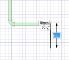
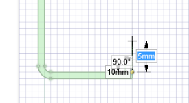
When sketching lines for a profile wall, the attachment edge for determining inside or outside radius follows the same paradigm as flat-sketched walls. In the images below, both lines start at the top corner. Sketching vertically downward creates an outside wall, while sketching vertically upward creates an inside wall.
Click on the Sheet Metal tab.
Click ![]() Line in the Sketch group or press L.
Line in the Sketch group or press L.
(Optional) Click the Profile option if you want to create walls as you sketch.
Click to set the first point of the line.
You can dimension the points relative to other sketch objects.
Click to set the next points of the line.
If you want any section of the line to be an arc, right-click and select Switch to Arc, then click to set the radius. Right-click and select Switch to Line to return to drawing straight lines between points. You must create at least one line segment before using this option.
End the line:
Double-click to set the end point of the line.
Right-click and select Finish Line.
Press Esc.
Connect the end point to the start point.
Click any tool (except the Clipboard and Orient tools).
Click and drag to draw one straight line.
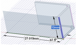
Sketching a polyline using the Profile Sheet metal option.
The following Sheet Metal sketch options allow you to choose between sketching a flat wall or a wall that is perpendicular to the sketch plane:
|
|
When sketching an open profile (series of lines), a perpendicular wall is created. When sketching a closed profile (square, circle, etc.), a flat wall is created. |
|
|
Any closed sketch creates a flat wall. |
|
|
When sketching an open profile (series of lines), a perpendicular wall is created. |
|
|
Use the starting location of the sketch to determine whether the inside or the outside of the sheet is maintained when bending. |
|
|
Maintains the length of the sheet's inside surface when bending. |
|
|
Maintains the length of the sheet's outside surface when bending. |
The following options are available for every sketch tool:
Cartesian dimensions: Select a point in a sketch and then click this option to see Cartesian dimensions from the point. Cartesian dimensions show you the X and Y distances from the point you select. If you don't have a point selected, it shows you the X and Y distances from the origin.
Polar dimensions: Select a point in a sketch and then click this option to see Polar dimensions from the point. Polar dimensions show you an angle and a distance from the point you select. If you don't have a point selected, it shows you the angle and distance from the origin.
Snap to grid: Select this option turn snapping on or off while sketching. The cursor will snap to the minor grid spacing increment while you sketch. The defaults are 1mm for Metric and 0.125in for Imperial units. See Units options to change the minor grid spacing.
Snap to angle: Select this option to turn angle snapping on or off while sketching. The cursor will snap to the angular snap increment while you sketch. The default is 15 degrees. See Snap options to change the angular increment used for snapping.
Create layout curves: The sketch curves are created as layout curves. If you move the design to a drawing sheet, with Sketch mode selected you must select the Create layout curves checkbox again in the Sketch Options group of the Options panel in order to create layout curves on the drawing sheet. See Layout Curves.
Curve Fitter Options: If the Sketch plane passes through a Mesh object, the system will fit curves through the facet points. Lines are displayed green and arcs are displayed blue. The following options apply to the system-generated curves.
Fit curves - Uncheck this option if you do not want the system to fit curves through the points.
Tolerance - Determines how many points will be found, which also determines how many curves will be created. The smaller the tolerance, the more points will be found and the curves will be generated.
Auto-merge - When checked On, the system will merge lines and arcs to form splines. Splines are displayed pink.
© Copyright 2016 SpaceClaim Corporation. All rights reserved.
 Auto
Auto Flat
Flat Profile
 Automatic
 Inside
 Outside